Continue to Site

Welcome to EDAboard.com

Welcome to our site! EDAboard.com is an international Electronics Discussion Forum focused on EDA software, circuits, schematics, books, theory, papers, asic, pld, 8051, DSP, Network, RF, Analog Design, PCB, Service Manuals... and a whole lot more! To participate you need to register. Registration is free. Click here to register now.

How to connect a digital panel meter and a dual variable power supply

Status
Not open for further replies.

jmx66

Member level 5
Joined
Nov 16, 2010
Messages
93
Helped
0
Reputation
0
Reaction score
1
Trophy points
1,288
Location
France
Activity points
2,045
Hi all,

First thanks guys for your help about a 340V dc power supply. Works fine :grin:


Now i built, with internet help , a power supply with 3 outlets:

- 2 variable power supply from 0 to 16 V : Works perfectly and digital panel meter works fine.

- problem is about a variable dual power supply....

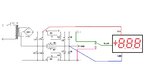
Schematic:**broken link removed**

My circuit is similar like this one , but with potentiometer added of course


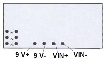
I found and bought on ebay, following panelmeter:

**broken link removed**


Made numerous trials but with no results.

Tried and checked on variable power supply, and the panel meter works correctly, but on the dual no result?????

Range is good and supply with 12 V ok


Who can tell me the right way to use it?


Thanks a lot.

jm
 

First you need to give more details about the ‘variable dual power supply’ schematics. In my opinion, that’s not the best solution if you are using 7812/7912 series ICs as a variable power supply. Please explain what does ‘’no result’’ mean when you connect the panel meter? And what’s the actually reading on the display?
 
  • Like
Reactions: jmx66

    jmx66

    Points: 2
    Helpful Answer Positive Rating
First thanks a lot for your reply.

Made a mistake on schematic joined.

The real schematic is this one: supply3.gif

As said previously, how to connect the panel meter, to read volt ?

U1 and U2 are LM317 and 337

Link : Dual Polarity Power Supply


Thanks a lot and happy Christmas.


jm
 

Can attach some pictures of the digital panel meter?
It’s not so clear if the panel meter use two or three wire to connect in the circuit.
A 3 wire standard connection:
 

Attachments

  • digital voltmeter.JPG
    digital voltmeter.JPG
    35.4 KB · Views: 154
As you are using two Pots for varying the output of your supply, (my suggestion) use Two Panel Meters independent to your output and if you want to use one meter then better use TWO variables GANGED together, so you can have better idea on your both the outputs having (almost) same output level voltage.
Made numerous trials but with no results.
Can you define what you mean by this?.
 

Hi all,

Thanks first for your replies.

Googled a lot and found " floating ground" , is there a mistake of my own about this?

Join datasheet for LDP140 LCD , the item has 4 wires + IN blue - IN green -5V black +5V red

98_1327605366.png


jm
 

Attachments

  • LDP_135_340.pdf
    116.3 KB · Views: 101

Some of the LCD panels are rather fussy about their power supply with reference to the input voltage, e.g. the ICL7126 family type LCD meters.
First try to use the panel meter from an independent 9V supply, like an external battery. See if that helps. If that is the case you need to make independent 9V supplies for the panel meters.

Good luck, Peter
 
Status
Not open for further replies.

Similar threads

Part and Inventory Search

Welcome to EDABoard.com

Sponsor

Back
Top