Continue to Site

Welcome to EDAboard.com

Welcome to our site! EDAboard.com is an international Electronics Discussion Forum focused on EDA software, circuits, schematics, books, theory, papers, asic, pld, 8051, DSP, Network, RF, Analog Design, PCB, Service Manuals... and a whole lot more! To participate you need to register. Registration is free. Click here to register now.

[SOLVED] Problem about Voltage drop at output of LM317 when load is connected.

Status
Not open for further replies.

Qaisar Azeemi

Full Member level 5
Joined
Feb 11, 2011
Messages
315
Helped
16
Reputation
32
Reaction score
15
Trophy points
1,298
Location
Peshawar, Pakistan, Pakistan
Activity points
3,829
Hi;

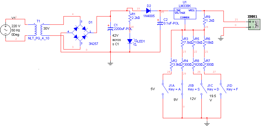
I am designing a power supply circuit using LM317 or LM338 voltage regulators. The problem occuring at the point when i connect a 2.7k resistor at the output which drop the voltages adjusted by the variable resistor between adjust pin and ground.

for example; i adjust 6.5v at the out put seen at the screen of digital meter. now when i connect 2.7k at out put of IC that is with the probs of meter, the voltages drop down to 3.8V but when i connect 10k it drops to 5.4V. i know very well that on load voltages will always drop then rated...........
but

the confusion is that to get 5V onload out put what should be the voltage across output of IC without load?

my specifications for supply are as follows:
5A supply that provides out puts of 5v, 9v, 12v and 19.5v.
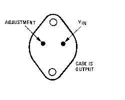
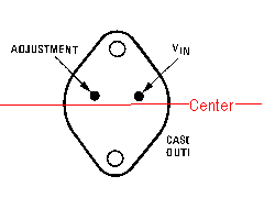
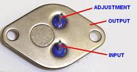
i amd using LM338k with 2.9k ohms resistor between output and adjust pins.
i am using a variable resistor and digital multimeter to adjust the out put and to find the value of resistors that should be connected at the place of variable resistor to get required voltage.

Expert suggestions and guidance is required.

Thank you
 

What is the input voltage?

The LM317T/LM317K/LM317AT/LM317S is a 3-terminal integrated circuit which can supply a load current of up to 1.5 Amps with an output voltage of between 1.2V and 37 Volts. It accepts an input voltage of between 3 and 40 volts.
As much as 2-3 Volts are dropped (lost as heat in the regulator) by an LM317T - i.e. if the desired output voltage is 7 Volts, the input voltage may need to be as much as 10 Volts if the output voltage is to be stable. This means that an LM317 voltage regulator cannot be used to provide a 12.0 Volt output from a 12V rated supply.

Dropout voltage- It is the minimum difference between input voltage and output voltage for which the regulator can still supply the specified current.

Another type of voltage regulators are LDOs--- A Low Drop-Out (LDO) regulator is designed to work well even with an input supply only a Volt or so above the output voltage. The input-output differential at which the voltage regulator will no longer maintain regulation. Further reduction in input voltage will result in reduced output voltage. This value is dependent on load current and junction temperature

**broken link removed**
The output voltage is selected using two resistors. Normally R1 is chosen to be around 220R or 240R. The formula for calculating the value of R2 is V = 1.25(1+(R2/R1)) or to put it another way R2 = R1((V/1.25)-1).

For example, for an output voltage of 8.5v. R2 = 220((8.5/1.25)-1) = 1276 ohms. The nearest preferred value to this would be 1K3.

Setting R2 to zero, ie. grounding the Adjust pin, will cause the output voltage to drop to 1.25v.

R2 may be replaced by a pot to give an adjustable output voltage range. The maximum voltage is approx. 37v although a higher voltage variant is available.

See **broken link removed**

For 5Amp supply consider LM138 series
or,
You may see this 5A constant current constant voltage regulator using LM317 :Few LM317 Voltage regulator circuits that has a lot of applications
 
Last edited:
It will be best if you drew a diagram of your circuit and upload it here. Otherwise, it's unclear exactly how you're trying to use the IC.

You mention only the resistor between the output and adjust pins. It cannot work that way. You also need a resistor from the adjust pin to ground.

Yes, the output should drop when you connect a load, but only by a VERY small amount. You're thinking of choosing a resistor that will cause the proper voltage drop. That's the wrong approach.

5-19.5V outputs from a 5V supply? That's meaningless. With series regulators like the LM317/338, the output voltage will always be lower than the input.

2.9k between output and adj pins is too high. These ICs need a minimum load of about 10mA. You have to use something like 100 to 150 ohms. But judging from your description, the rest of the circuit is probably wrong too. It seems you're using the configuration for a current regulator, not a voltage regulator.
 

Regulator regulates ouput voltage from 0 to full load at the set level. Input require 2=3 volts higher than the maximum output required. There is protection circuit for over current bilt in IC. If you draw more thn 1.5A(see datasheet) then output voltage will drop accordingly, not letting current to rise beyond that point.
Calcultor to easily get the value of resistors.
**broken link removed**
LM317 / LM338 / LM350 Voltage and Current Regulator Calculators

Probably you are drawing more current than allowed.
 
Last edited:

I am attaching the image of my circuit below.


this circuit is completly describe the situation. i am using LM338 because i need 5A current to drive my laptop and LCD Screen.

input voltage after 2200uF cap is 42V. that are applied to LM338 and i want to get 5V, 9V, 12V(For LCD), and 19.5V(for Laptop).

Prooblem is that by connecting a Load of 2.7K the voltage at output is droping.

im also using LM317 calculator now as suggested by Mr.Alterlinks and Mr Papunblg.

Mr Pjdd: the input to the IC is high enough and out is much less than the input.

NOW

PLZ Tell me Should i check the Output of LM338 with load or without load before implementing the circuit on PCB. means should i consider the no load reading at DMM final and ok, no matter how much the voltage is dropped by load after that?
 

D2 is only 1A diode. Secondly it is not required. +ve from C1 should go directly to ic input. Bridge is good only upto 2Amps. For the LM338 regulator, 120 ohms is typically used for R9 not 1.2K and then get values for R2-R7 for required voltage output. Keep in mind, maximum input voltage is 40v.
LM2576 is a switching regulator ic. It operates with less losses.You can consider it for your project. As at 5V 5A output there is more than 30V drop on IC equals more than 150 Watts to dissipate as heat.
the confusion is that to get 5V onload out put what should be the voltage across output of IC without load?
should i consider the no load reading at DMM final and ok, no matter how much the voltage is dropped by load after that?
As i early stated,
Regulator regulates ouput voltage from 0 to full load at the set level.
In datasheet,
VRLOAD Load Regulation from 10 mA to 5A load only drift willbe 0.1 to 0.3 %
That means for 10V you will see only 0.3V drift.
 
Last edited:

There are some things that are not optimal with your circuit for practical use, but it should provide the desired output voltages without load or at light load. Are you sure you have the IC pins connected correctly?

As I said before, the output voltage should change only by a very small amount (something like 0.1V or less) from no load to full load. If it still changes by a large amount between load and no load, there's still something wrong. A load of 2.7k should produce practically no change in the output voltage.

Another thing I mentioned before is that the LM317/338 needs a minimum load current. If you have a load connected permanently to the output, that's fine. Otherwise, change all the voltage setting resistors to one-tenth of the values shown. That is, change 1.2k to 120 ohms, 3.9k to 390 ohms, 10k to 1k, and so on.

Other points:

1) D2 is a 1-amp diode, so it will not be able to deal with the full load current you need.
2) If you actually draw several amperes from the circuit, there will be a large power loss in the regulator IC and that will have to be dissipated as heat. You'll need a huge heatsink for that. This is why switched-mode power supplies are used in many applications as they have a much lower power loss.

Edited: I see that Afterlinks had said pretty much the same things I did while I was typing my reply.

Hurrrrraaaa :)
PROBLEM SOLVED


i just changed 1.2k with 220ohms.... keeping rest of IC configuration same....

Thanks alot to my all friends who replied me.

yes MR Pjdd... connections are correct. and D2 is just used in simulation practically i will use 5A rectifier diode... i am using it for another purpose that is not included yet.

Thanks very much to all.

---------- Post added at 15:09 ---------- Previous post was at 15:00 ----------

D2 is only 1A diode. Secondly it is not required. +ve from C1 should go directly to ic input. Bridge is good only upto 2Amps. For the LM338 regulator, 120 ohms is typically used for R9 not 1.2K and then get values for R2-R7 for required voltage output. Keep in mind, maximum input voltage is 40v.
LM2576 is a switching regulator ic. It operates with less losses.You can consider it for your project. As at 5V 5A output there is more than 30V drop on IC equals more than 150 Watts to dissipate as heat.

Thank you alertlinks for your kind guidance. my problem is solved by just replacing 1.2k with 220ohm. you are quite right the drift is now negligable.

for 5V ... the amperage will not be such high. i just need high currents for LAPTOP and LCD screens. rest of devices are of low powers i.e; less than 1A.

1A diode is only use in simulation. i will use 5A diode here. it is for another purpose that i not included in my diagram yet.

than you very much again :)
 

Checkout this tutorial.

About regulators,
 
Last edited:

I know very well about using these all voltage regulators. i have used LM338T as shown in this video, and it worked very well. i am actually confused in using LM338K (TO-3 steel package just like 2N3055 Transistor package) i am totally confused in recognizing the adjust and Vin pins even after looking at data sheet.
please guide me about that.
 

83_1322830140.png

Pins are not in exact center but slightly towards one corner. Hold in your hand in such a way that pins are towards your face and pins are in upper half like in picture
.
57_1322830488.png

The left pin is adj. Right is input and body is output.
 
Wait... what AC transformer are you using? Because symptoms which you have described look nothing like insufficient power rating of the transformer. To get 5V 5A and given that your transformer outputs 30V RMS (i assume) then the current would be as high as 3.5A RMS which gives 105 VA. That is quite a big transformer.

edit:
Also, as it was mentioned this will dissipate anormous amounts of power as heat. If transformer gives you 30V RMS, this is ~42V or peak voltage, which gives about 40V at b ridge output and about 39V at regulator input thanks to the diode (btw, what input voltage can the LM338 tolerate?) If you set things to get 5V and 5A, then voltage drop across regulator is 34V, which at 5A of current translates to 170 W of power loss. This is huge. You are going to need at least a 10x10 cm heatsink with a fan + good thermal contact of LM338 with heatsink (need to use thermal conductive paste).

I'd better thin about some switch-mode supply. This kind of supplies have high efficiencies approaching up to 95%
 
Last edited:

Alertlinks already posted drawings showing the pin orientations. Here's an actual photo. The point to remember is that the pins are not in the center. They are closer to one end than the other and that's the key to indentifying which is which.

61_1322845373_thumb.jpg


Also remember that the main case metal is the output terminal and is not grounded. Heatsinks are usually grounded. Therefore, if you mount the regulator on a heatsink, the case must be insulated from the heatsink.

Regarding the problems you mentioned in your PM, check your wiring carefully. See if you have the capacitor polarity connected the right way. A reverse connection can blow it up. Also check the bridge rectifier (D1 in your diagram) and see if it has become shorted. A shorted rectifier will pass AC to the capacitor instead of DC and can also cause it to blow up.
 

Status
Not open for further replies.

Similar threads

Part and Inventory Search

Welcome to EDABoard.com

Sponsor

Back
Top