Continue to Site

Welcome to EDAboard.com

Welcome to our site! EDAboard.com is an international Electronics Discussion Forum focused on EDA software, circuits, schematics, books, theory, papers, asic, pld, 8051, DSP, Network, RF, Analog Design, PCB, Service Manuals... and a whole lot more! To participate you need to register. Registration is free. Click here to register now.

Op Amp based Hartley oscillator design

Status
Not open for further replies.

udushu

Newbie level 2
Joined
Nov 29, 2011
Messages
2
Helped
0
Reputation
0
Reaction score
0
Trophy points
1,281
Activity points
1,299
Hi all,

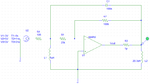
I have a design of the Op-Amp based Hartely oscillator that I can't get working. The design is attached to this post.

I have made the simulation as of the oscillator, I believe it should oscillate, since the gain of the Op Amp negative feedback loop is greater than L1/L2 ratio and I estimated the Q as ≈7800. But the oscillations start and die. I can see that the frequency of the decaying oscillations is correct, but they would not sustain.
I event tried to boost the gain up to some unreasonable number, but this doesn't help at all.

Can anyone advise me, what I'm overlooking and how to make this circuit oscillate?

Thanks.
 

Attachments

  • opAmpHartleyOscillator.png
    opAmpHartleyOscillator.png
    18.1 KB · Views: 120

U2 is a pulse generator required to start oscillations. Due to the initial conditions oscillations typically should not start in simulation.
 

Hi Udushu,

Three questions:
1.) What is the desired frequency?
2.) Are both inductors coupled (same core)?
3.) What is the meaning of the "resistor" with a value of 1E-12 ohm?

---------- Post added at 09:34 ---------- Previous post was at 09:29 ----------

Another question/comment:
Don't use a voltage puls to start the circuit. When the puls disappears the resistor is grounded and causes strong damping.
Instead, use one single current pulse.
 

If the resistor is 1 pico-ohm then that's very low. The oscillating loop is getting swamped by the op amp output.

The oscillating loop benefits from having a certain amount of isolation. On one end at least.

The kick from the amplifier should only supply just enough boost per cycle, to restore lost energy in the coil and capacitor network.

Experiment with various output resistance amounts. A potentiometer will make this easy.
 

with the calculation that i made you are planning to design 1 Mhz oscillator.....correct me if I am wrong....in my view if you are using 100nf capacitor .....use box type capacitor....i think you are using disc capacitor .....generally disk capacitor have very low charge storing capacity....

Good Luck
 

If the resistor is 1 pico-ohm then that's very low. The oscillating loop is getting swamped by the op amp output. The oscillating loop benefits from having a certain amount of isolation.
Setting a resistor value to picoohm (microohm would be effectively the same in this case) is a common method to remove it temporarily from a simulation circuit, because zero ohm isn't allowed by the simulator.

I won't say the oscillation loop is swamped, but in fact the resonator isolation is superseeded, or in case of an ideal OP, one inductor is simply shorted. In other words, the resonant circuit is reduced to a single LC topology. As a result, the LC phase shift is smaller than 180° and the oscillation condition can't be fulfilled, at least for an ideal OP.
 

.............................
or in case of an ideal OP, one inductor is simply shorted. In other words, the resonant circuit is reduced to a single LC topology. As a result, the LC phase shift is smaller than 180° and the oscillation condition can't be fulfilled, at least for an ideal OP.

Yes, the first inductor of the LC Pi-network is useless if connected directly to the output of an opamp. In Colpitt and Hartley oscillators these networks are designed for CURRENT sources (like BJT and FET). However, an adaptation to voltage amplifiers is possible by introducing a resistor (not pico-ohms !) in between.
I know that in this respect the circuit descriptions in some books are incorrect.
With this additional resistor the circuit should oscillate - provided UDUSHU does NOT use a voltage puls for excitataion of the circuit (my former posting #4).

---------- Post added at 10:18 ---------- Previous post was at 10:05 ----------

The value of this resistor is relatively uncritical (100...1k) - it determines the sharpness of the loop gain around wo only (quality factor).
 
Last edited:
  • Like
Reactions: FvM

    FvM

    Points: 2
    Helpful Answer Positive Rating
Status
Not open for further replies.

Similar threads

Part and Inventory Search

Welcome to EDABoard.com

Sponsor

Back
Top