Continue to Site

Welcome to EDAboard.com

Welcome to our site! EDAboard.com is an international Electronics Discussion Forum focused on EDA software, circuits, schematics, books, theory, papers, asic, pld, 8051, DSP, Network, RF, Analog Design, PCB, Service Manuals... and a whole lot more! To participate you need to register. Registration is free. Click here to register now.

Problem with 5W 2sc1971 RF amplifier

Status
Not open for further replies.

doug08

Junior Member level 3
Joined
Jun 4, 2010
Messages
26
Helped
1
Reputation
2
Reaction score
1
Trophy points
1,283
Location
Florida
Activity points
1,506
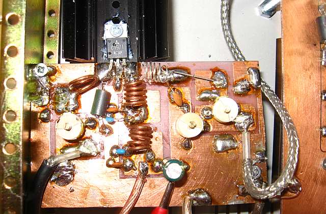
I made this 5W RF amplifier, but I have a problem of the amplifier not drawing steady current. According to the design/schematic, I need a few hundred mW of input power to get the full 5W output. I have several low power transmitters(50 - 400mW) laying around that I tried, but it does not work. I also have a 50 Ohm 10W dummy load that I made just for this amplifier. I have made several others under 5 watts which all work fine.....but this one is a mystery. I tested the transistor and all components to make sure the values are correct. I also made sure there are no shorts. The housing to shield the circuit could not be built better. Hopefully someone here knows what the issue is. Only thing I can think of is that I am not sending enough mW to the input to get it going, or the way I am connecting the low power transmitter to the RF amp is the problem. Please check out the link to my video.

Thanks.

SNV31226.JPG
SNV31224.JPG
SNV31236.JPG

SNV31223.mp4 video by whereisdbn - Photobucket
 

It looks to me as though your 400mW source and what looks like a 9V battery are connected in series, the negative pole of the battery going to your "ground" and the r.f. port of the source going to the amplifier's input, no other connections.

If that observation is correct ... the wiring is incorrect. There should be both positive and negative leads between the battery and the 400mW source. The r.f. feed to the amplifer would be better via co-ax.
 
The 9V battery powers the small 350-400mW transmitter. I took the antenna wire from the transmitter(which has the last 1/4" stripped to bare copper) and fed it into the center of the coax connector on the input of the amplifier. I took the negative from the transmitter circuit, which is also the negative of the 9V battery, and connected that to the outer portion of the coax connector/amplifier ground. I though both units needed to have a common ground?

Thanks
 

I'm no expert on HF amps but, like Syncopator, I feel that you should have a better way of coupling the lower power transmitter to the amp. Maybe losses in the coupling is preventing the power amp from receiving the proper drive level. What frequency are you trying to pump out?
 

I live on an out island in the Bahamas. I have a TV video transmitter that I will be using. Many unused channels here. I was only using the low power FM transmitter to test the amplifier to make sure it works.
 
I agree with the other comments. The "flying leads" source connection is likely to cause amplifier self oscillations, particularly because the ground connection of the output jack is also far from being perfect, with a huge built-in ground inductance.
 

5W means 37dBm.

The power Gain of 2SC1971 is about 10dB.

So, to get 37dBm (5W) at the output you have to drive it with 27dBm (0.5W).

To get a true 0.5W drive power, perhaps you have to use a 1W power transistor, because for sure in your not tuned interstage matching network you lose at least 3dB (half of the power).

In front of the driver you can place a low power transistor (<100mW)
 

It is good practice to wind iductors with equel space in turns. Try adding bypass capacitors in supply lines on board. Change the orientation of base coil(1 turn). Ground heatsink.Set variable capacitors to minimum initially. Determine if it is self oscillating or simply not giving output. If it is not giving any output, be sure transistor is not a fake.It happened to me when it was not even a bjt, but a fet printed with this part no.
 
Last edited:

The preferred connections between the 9V battery, 400mW source and the amplifier would be separate pos and neg leads source to battery, and the co-ax properly connected (signal and screen) at both ends.

Since you are sure that the power transistor is still ok, there can be little between it and the source to fail. Can you look for r.f. with a 'scope or other indicator on the path between the input co-ax connector and the transistor?
 

The connectors F-Type so they are 75 Ohms CATV connectors..
A small remark
 

Assuming a 50Ω source, 50Ω cable and 50Ω input to the amplifier, with 75Ω connector at the amplifier's input there will be a 1.5:1 v.s.w.r. at the cable/connector interface, and at the connector/amplifier input interface - at least theoretically.

However v.s.w.r. of 1.5:1 represents 4% reflected power - very unlikely to be the problem here.
 

Ok. The heat sink is grounded to the housing. so that is good. I know the coax has an effect on impedance, but it is hard to believe that my cable RF connector would cause any problem. Any other RF connector is constructed basically the same. I have heard about fake RF transistors. I did get it from China. I tested the RF transistor with my Wavetek DMM, and my DCA55 component tester. The component tester shows a fully functional NPN transisitor with an hfe of 10. Sounds low to me. According to the schematic, you wind 2 coils 6T on 5mm form, 1 coil 1T on 5mm form, and 1 coil 5T on 5mm core. They did not say to leave a wires width spacing between the turns(as other RF circuits I made said to do). I agree the 1T coil is kinda close to the trimmer, but I made sure it did not touch the trimmer. That should be ok. The schematic states that .5W will give the full 5W output of the amplifier. I do have a Velleman hps50 scope. I recently got it. Can I use it to test this circuit out? If so, where do I place the probe, and what setting for time/voltage?

Thanks for all the help!
First.. your "space mounting" is too bad...Especially ground connections are not acceptable..
Second connectors made in china have very RL..typ. 6-10dB and 75 Ohms...you will loose too much power..
Third, If Bf of the transistor is 10, it's probably burned..
Fourth, the body of these type of transistors are generally emitter and should be tightly grounded...
The trimmer capacitors are "jurassic park" style and since 30 years nobody usese them anymore.. how did your get them ?
etc. etc..
I recommend you first of all.. read something about "design and implementation of RF circuits" from different sources, for instance ARRL Handbook, ANs of different Companies for instance NXP, Motorola, etc..You can not implement a RF circuit just connecting the nets..

A typical PA should at least look like this...1971.jpg
 
Last edited:
  • Like
Reactions: FvM

    FvM

    Points: 2
    Helpful Answer Positive Rating
There are minor and major problems. Using a 75 ohm connector with a 50 ohm cable at VHF frequencies places a small discontinuity and isn't a big thing, but of course worth to mention. Bad ground connection of the connector as shown here is much more severe. You can calculate the effect in terms of inductance, if you like to.

Before making comments on the involved parts, I would prefer to know the operation frequency, which wasn't yet told. How did you determine the inductor number of turns. I see, that the circuit is similar to the 175 MHz data sheet example.

Mounting parts above a ground plane, either on a PCB or a "baking sheet" basically isn't bad. "Space mounting" adds series inductances that have to be considered. It becomes bad, if too much coupling between amplifier in- and output is created. That may be a problem here, but I guess, that the unwanted coupling created by the flying lead input ground is much stronger.
 

Assuming a 50Ω source, 50Ω cable and 50Ω input to the amplifier, with 75Ω connector at the amplifier's input there will be a 1.5:1 v.s.w.r. at the cable/connector interface, and at the connector/amplifier input interface - at least theoretically.

No, not even theoretically. You cannot do the math like that. The connector is a piece of line, not a wideband resistor of some kind.

To calculate the VSWR, you need to calculate the impedance transformation based on the 75ohm segment's length. Here it is very short compared to the wavelength, so it doesn't really matter what connectors you have, as long as the lines and the input/output terminations at the end of the line agree.
 

and what sort of power supply are you using for the amplifier ? what voltage and current rating.
if this is for 150MHz and higher then you cannot use the sort of interconnections that you have done.
as others have stated it must be coaxial links between driver and amplifier. your style of connector connection
to the PCB with these higher freqs is not good to say the least.
Have you got a proper power meter suitable for the freq of use ? you still havent answered the question as to what freq ?

long leads from your power transistor to the PCB for VHF/UHF freqs are bordering on unacceptable. They must be as short as possible

cheers
Dave
 

Frequency used is between 80 - 175mhz. I have a filtered DC power supply of 13.85V/up to 2A. People here are stuck on this problem of the way I TEMPORARILY connected up my small rf transmitter to the amp ONLY to test is out. Keep in mind that I already made two 1W versions that work perfectly(TESTED THE SAME WAY!). They are constructed the same exact way, using the SAME coax connector, and I saw no problems using them. The 50 ohm connectors are made out of the same brass, and the center conductor in them is also brass surrounded by nylon....like the 50 Ohm connectors. I personally cannot imagine these connectors causing any problem, especially because they are only a tiny part of the entire feed line. A very small loss I can live with. I connected a 50 ohm dummy load to my 1w units using the same rf connectors........SWR was a hair over 1. When I used my antenna instead, it was 1.3:1. As for the capacitors, ever hear of the saying, "You have to make do with what you have"? That is exactly what I did here. Bottom line, they work. Obviously the transistor's body is tightly connected to the grounded housing/heat sink using thermal compound. Next case....I do not have fancy RF equipment. When I tune my RF amplifiers, I use an RF signal strength meter, a RF counter w/built-in strength meter, and a DMM to monitor the current into the amplifier. What I do, with success, is tune the amplifier until I get the maximum possible RF output, for the least amount of current draw. As for the transistor not being closer to the board.....I placed it as close as possible so I can still place a heat sink on the lead that I solder to the board. My layout to me looks fine, with the exception of the 1T coil being close to the trimmer. I agree with that. What could possibly be wrong with the way I grounded each RF connector to the board? How else can you do it? Bottom line, I have a sneaking suspicion that my 2sc1971 transistor is a fake. I read online that many Mitsubishi RF transistor fakes on the market. I think I'll try another RF transistor in place of the one currently installed. If everything works fine, then that was the problem. Also, the schematic did not tell me to leave spaces on the coil turns as other schematics have. That is why they are tight. I followed instructions.

Thanks
 

Your problem is not high ratio of standing waves as mostly discussed but you have no power at output.
29_1322664276.jpg

A working amp not better than your construction.

89_1322664452.jpg
95_1322664452.jpg
92_1322664452.jpg

12V bulbs can be used to monitor power.
Operating amplifier without load can destroy transistors in an instant if it is oscillating and is without load. One of my transistor destroyed in such a way that it was ok with meter, even ok at low frequency but did not operated at vhf.
You should connect input using coax cable or put driver circuit very near to amp and then connect signal and ground with small bridges. Adjust and rotate coil at base so that it is not in line with output inductor otherwise it will pick up feedback and cause self oscillation. So dont operate without first connecting load. The way input is provided, only cause self oscillation and minimum drive, a major cause of transistor damage. Initially set maximum current from power supply around 200mA while testing.
 
Last edited:
  • Like
Reactions: FvM

    FvM

    Points: 2
    Helpful Answer Positive Rating
Thank you. That was my point. Your works, and mine is a much neater/cleaner job, so why would mine not work? Makes no sense other than my transistor is fake.

Here is the schematic:
(Notice his transistor legs are just as long as mine.....his works just fine). I cannot figure out why his board has more components than the schematic shows.

**broken link removed**
 
Last edited:

As your amp worked initially, so the transistor is probably not fake but destroyed by not protecting against over current drawn due to providing with unbalanced input and may be not connected with a load. Follow precautions to operate at high power against damage.
 

Status
Not open for further replies.

Part and Inventory Search

Welcome to EDABoard.com

Sponsor

Back
Top