Vermes
Advanced Member level 4
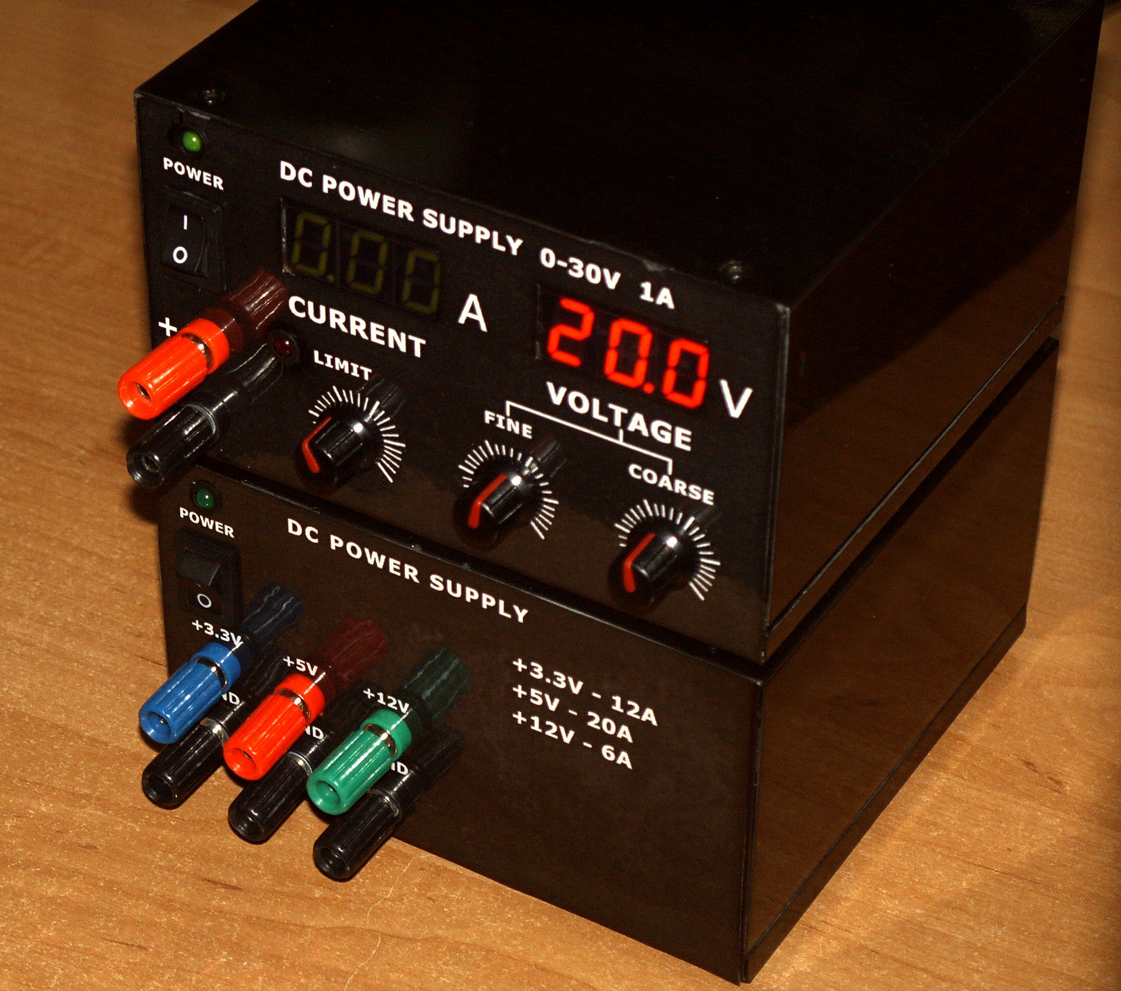
Generally about the device
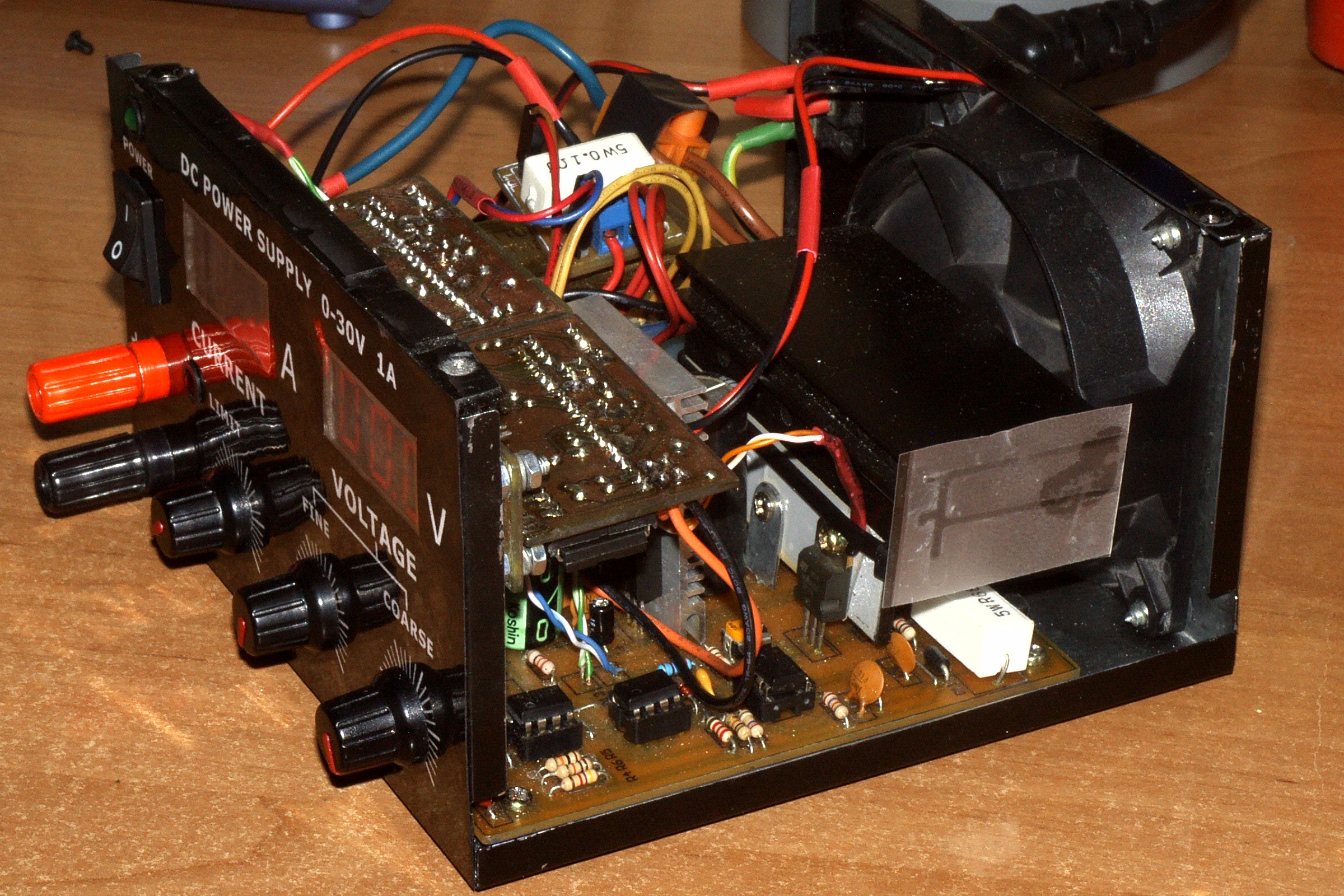
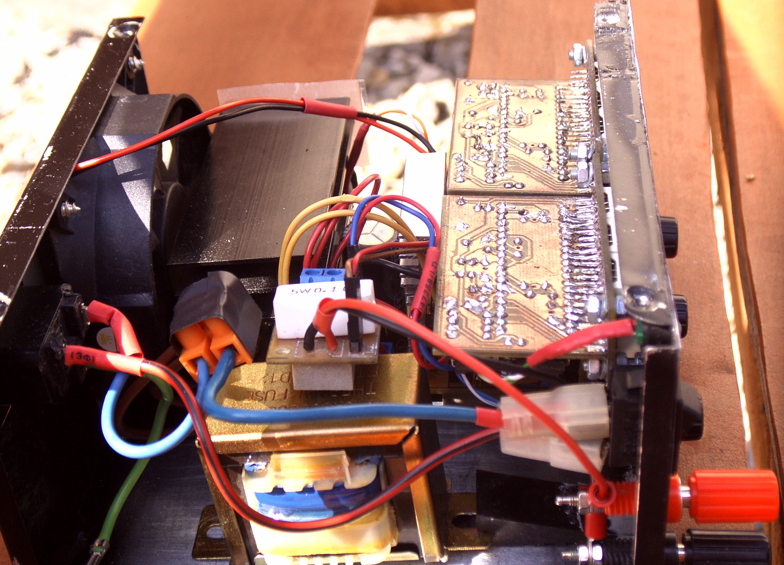
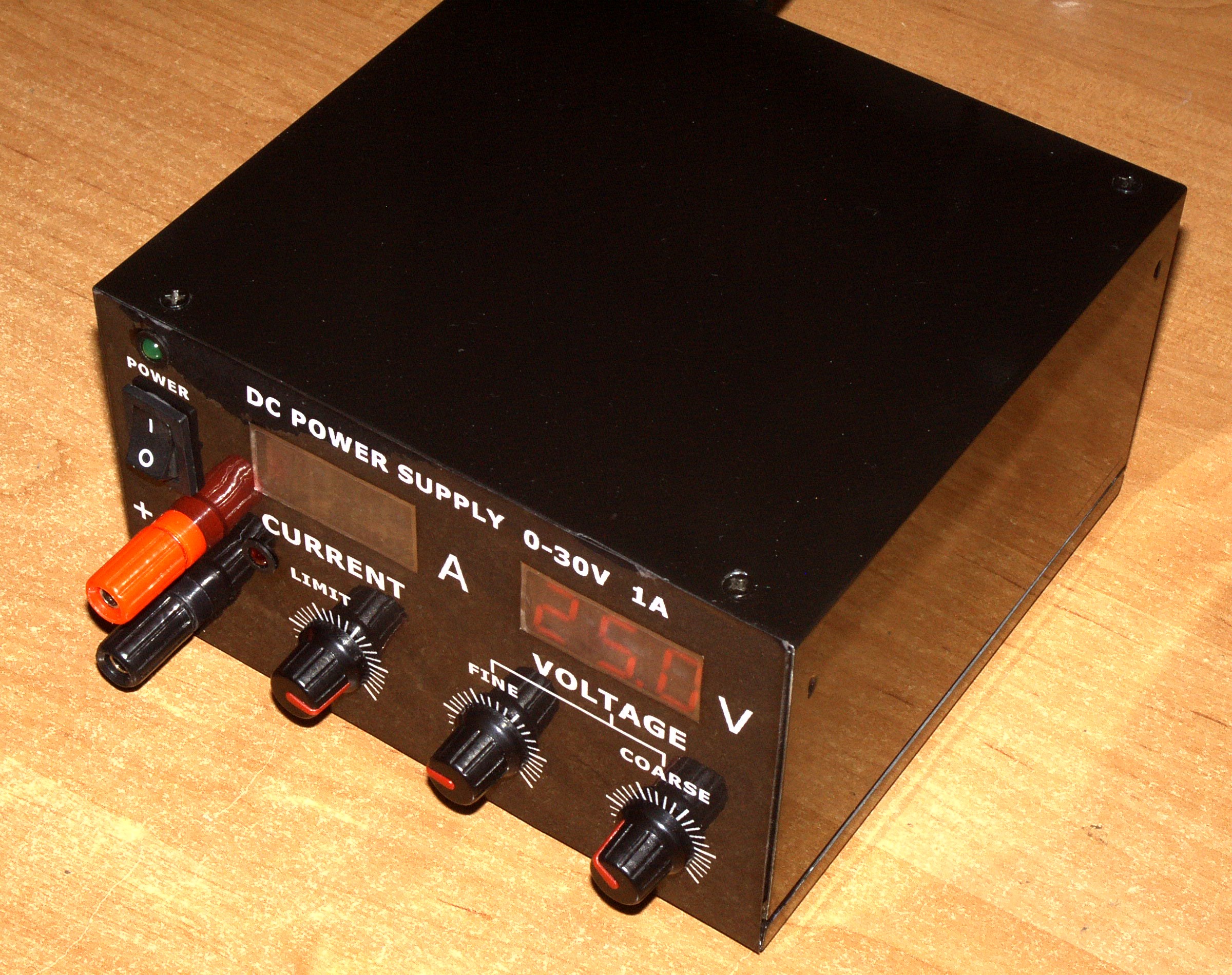
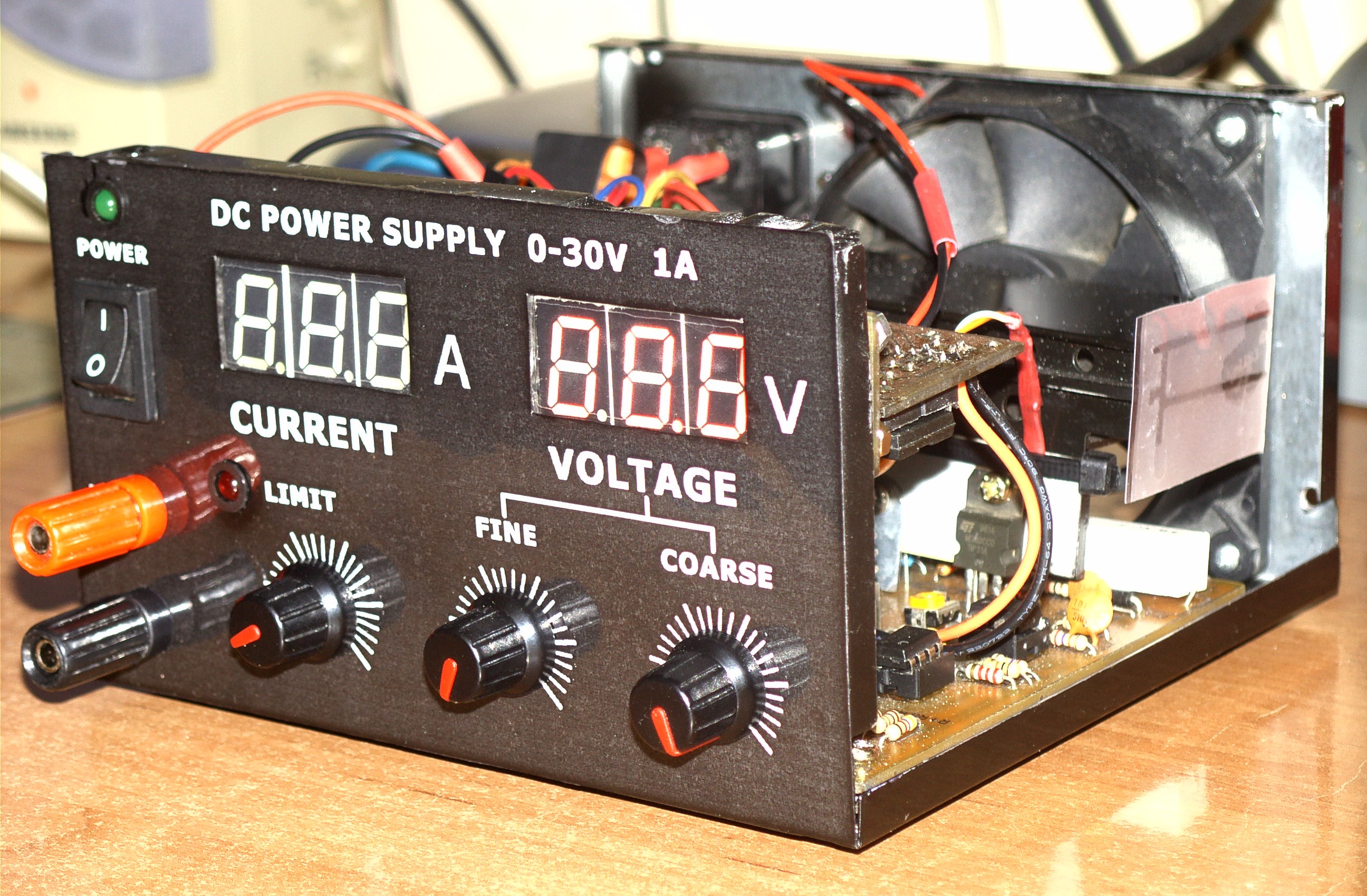
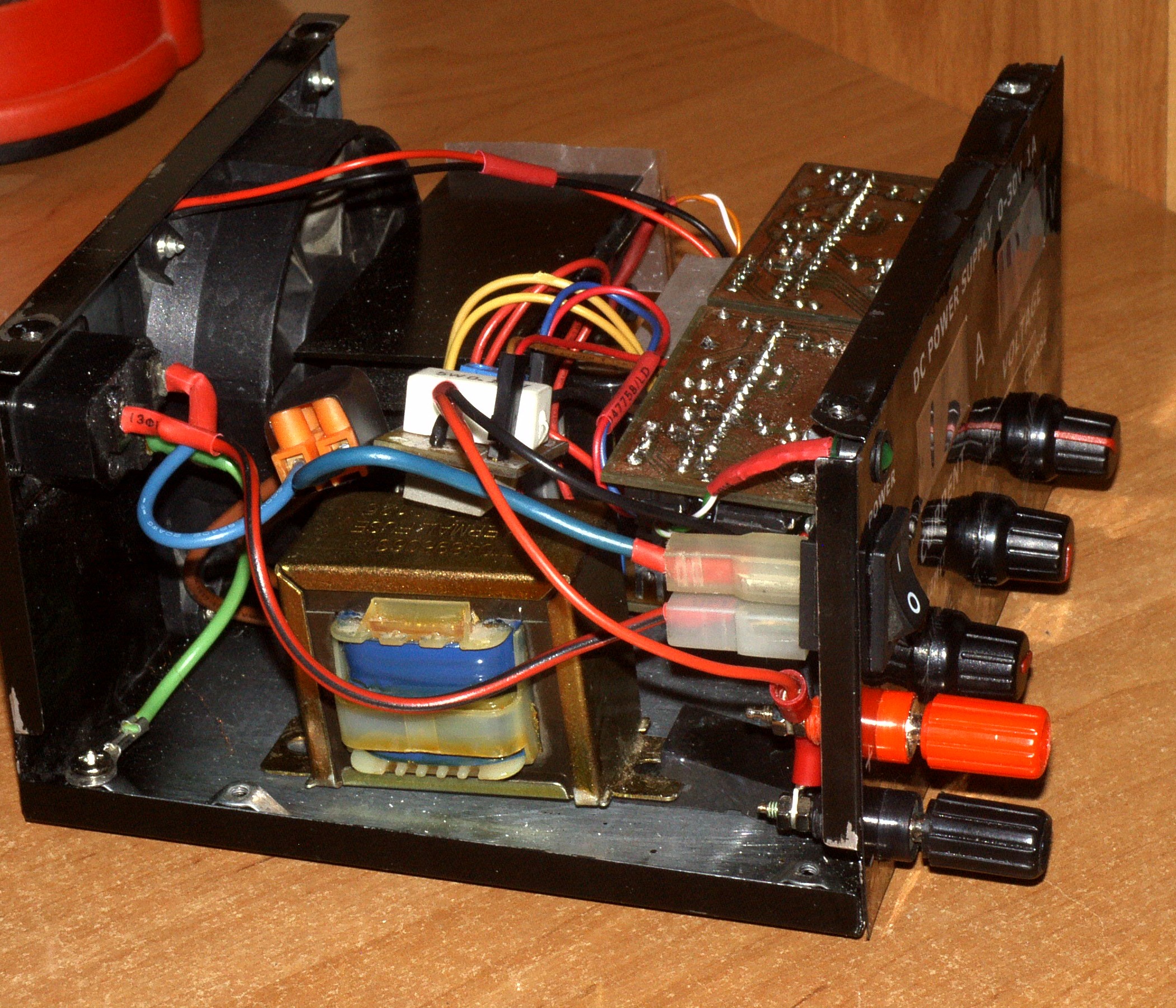
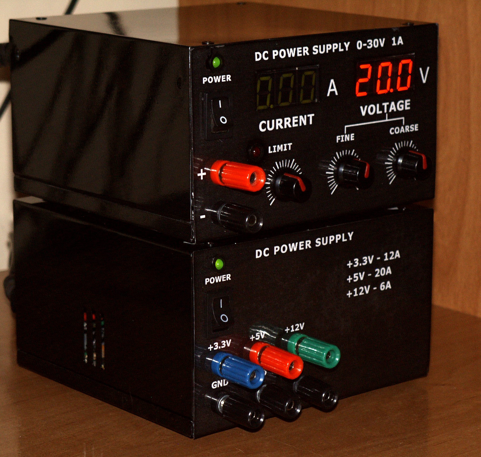
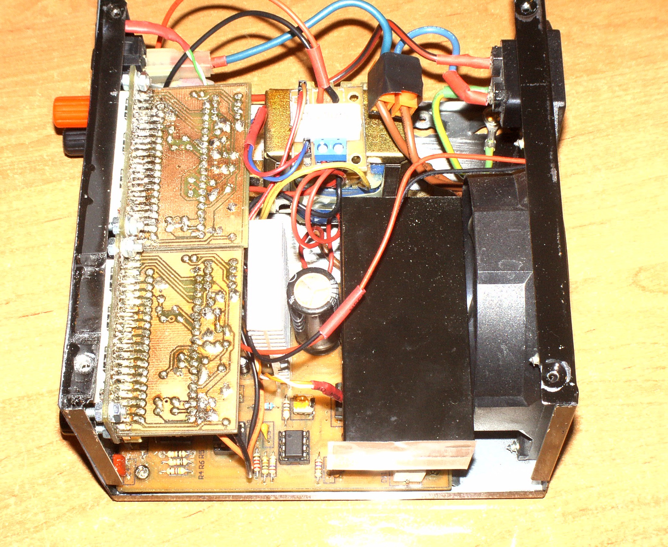
The power supply is a well-known design from electronics-lab, along with popular measures on the ICL7107 circuits and a fan thermoregulator. Several changes were made in the construction of electronics-lab, including increasing the resistors R7 and R18 values, which contributed to the smooth adjustment of the current limit to 1A. Also power transistor was changed to TIP31A and diodes with current of 2A for size and savings reasons. The fan thermoregulator was made on basis of the stabilizer LM317 and thermistor NTC placed near the power transistor. On the main circuit board there was also placed auxiliary power supply for the meters and thermoregulator, made on the rectifier bridge, filtering condenser and stabilizer LM7805. Both stabilizers were placed on a small heat sink, which heats up quite a lot. Auxiliary power supply is connected to a separate transformer taps, what gives 12VAC. Shunt is made of resistor 0,1ohm 5W and guarantees fairly stable readings.
PCB
All the PCBs can be designed on your own. They were made in thermal transfer method.
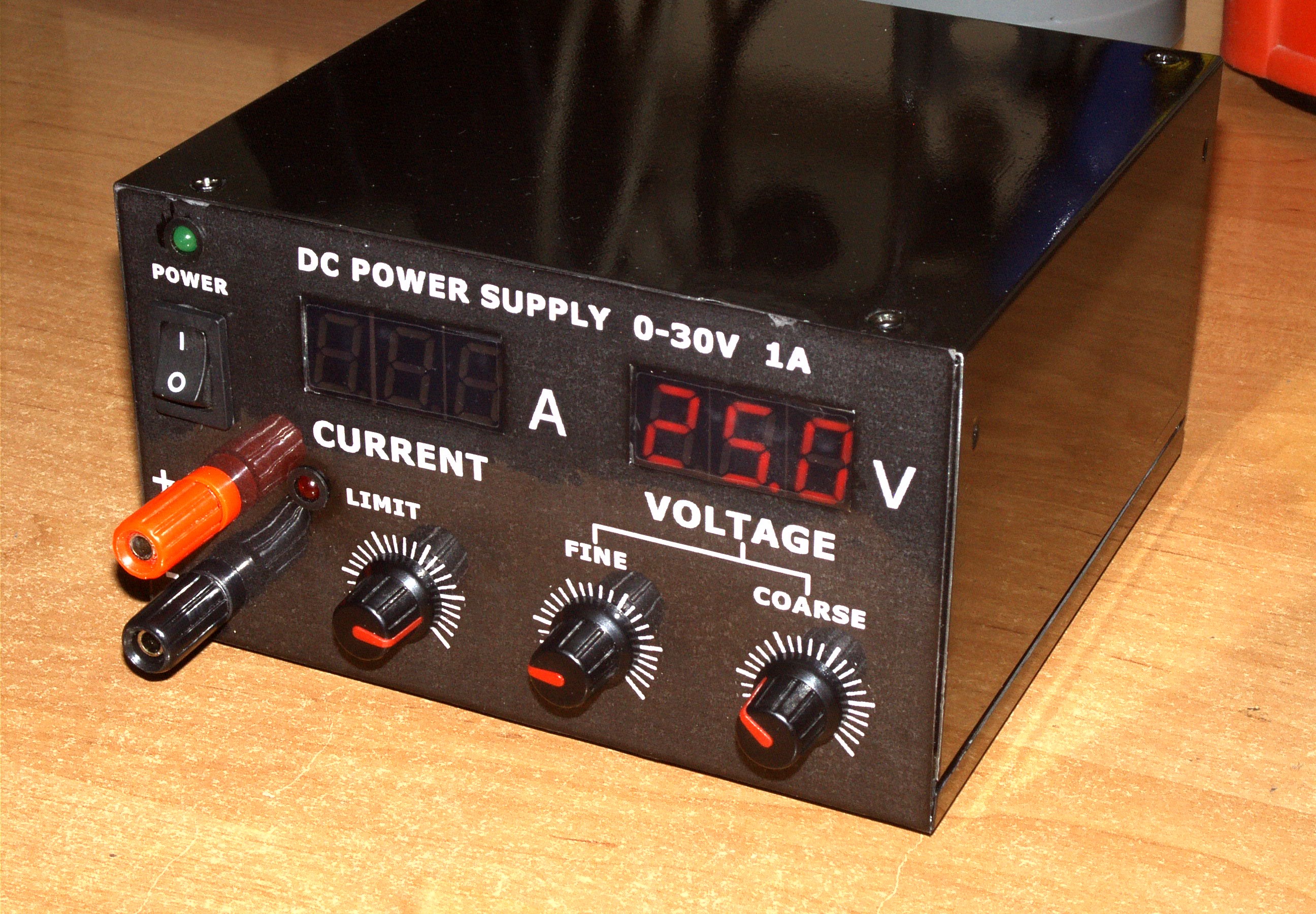
Housing
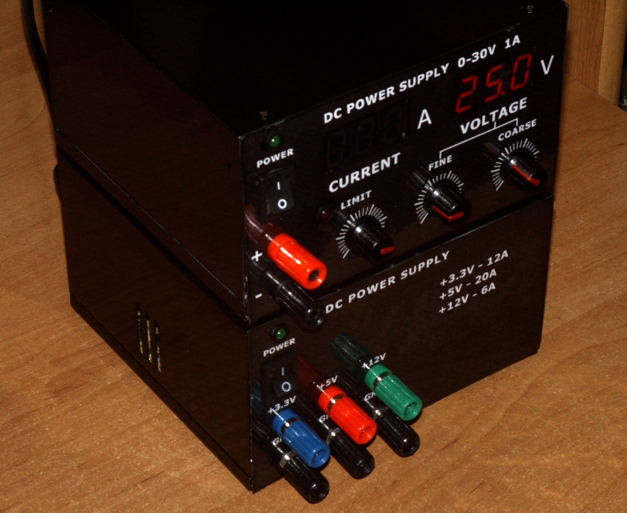
Housing was taken from an old ATX power supply. Unnecessary holes were filled with shields, which were soldered and filled with polyester resin. The whole was painted black with acrylic paint. The front panel does not look perfect (no solid color), mainly poor print quality and bad foil welding in lamination process are responsible for that. Laminate fell apart when cutting holes, so it had to be hand-welded with iron once again. Film for dimming glass was used as display filters. Panels were designed in GIMP 2.
Processing of an old ATX power supply
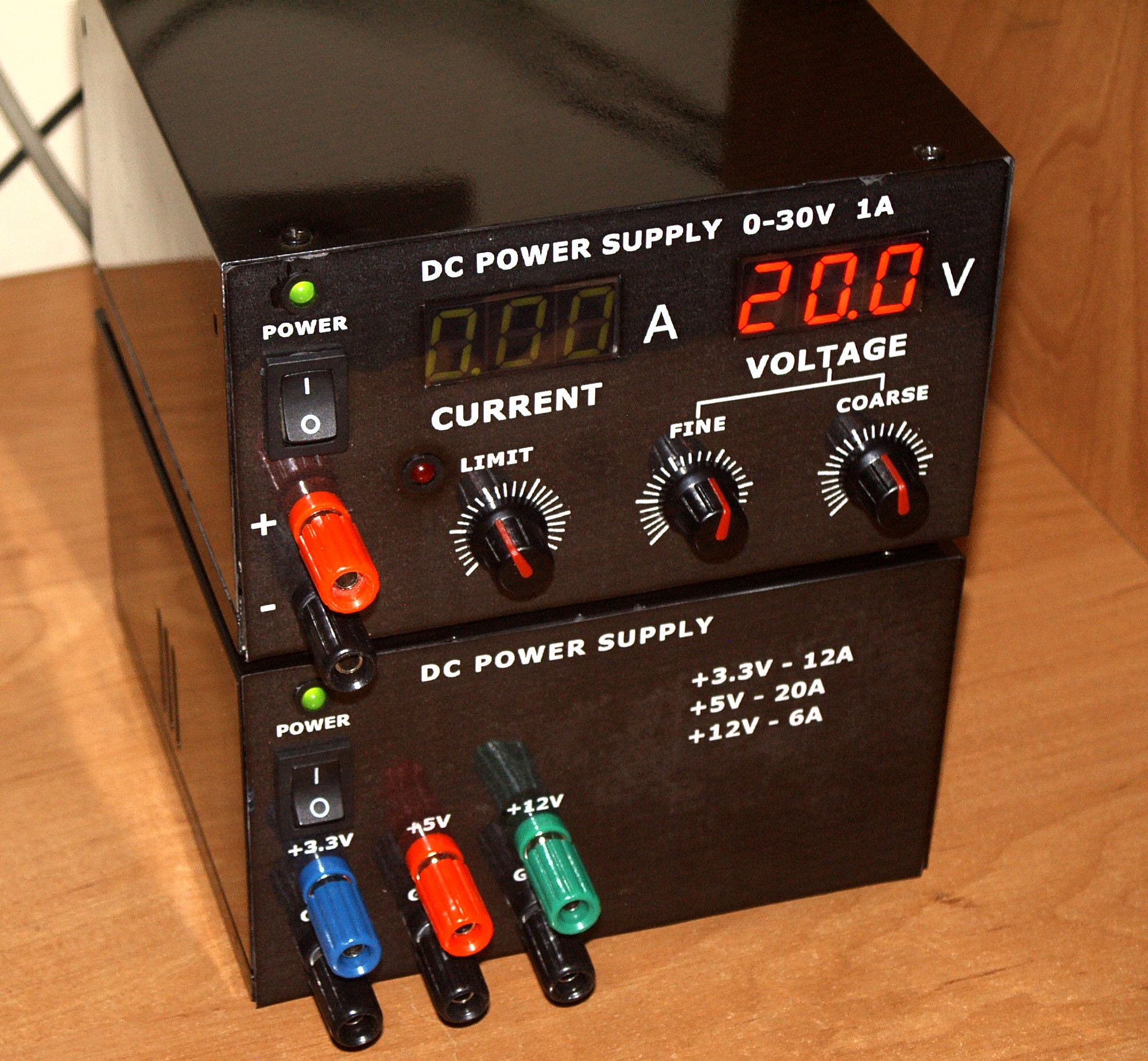
Minor changes were made to an old ATX power supply. Sockets, diode signalling operation and the mains switch were placed in the front panel. Right connectors were shorted, so the power supply can work immediately after turning the power on. It works properly as power source for a PCB drill.


Link to original thread (many useful attachments) – Zasilacz laboratoryjny 0-30V, 1A + przeróbka zasilacza ATX
Last edited: