Vermes
Advanced Member level 4
It is a HF power amplifier on the lamp GU 81. The system has control on the grid, class AB1 (the grid works only for negative voltages). At the input, adapting the driver filter “pi”, parallel power supply of the anode, the output filter “pi” allows the amplifier to the antenna.
Automatics realized on the power contactors, which implements:
- the gradual start of high power supply (without that, it throws the plugs in home installation)
- the sequence of providing the voltages to the lamp: glow, first grid, anode and second grid – providing the voltage to the second grid without anode voltage can damage the power supply of the second grid – the lamp would be okay
- control the antenna relays
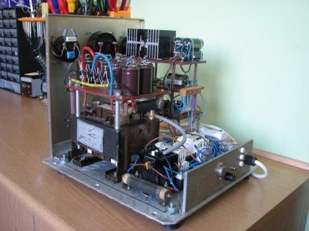
The lamp GU 81 is a Russian power pentode and it is not one of economical lamps. To glow, it needs 120W (12V/10A – a typical toroid transformer). In the control system, in the grid, beyond the anode voltage (and the incandescence) it still requires two grid voltages: 1 grid (control), 2 grid (screening) and 3 grid (inhibitory) connected to the mass. Anode power supply was made as a full wave transformer (2330V/0,62A) from an old microwave oven: there are 5 diodes 1000V in each branch of the bridge, 10 electrolytic capacitors together with 10 resistors, that divide the voltage between the capacitors and discharge them after power is turned off. The anode voltage is fed through a resistor, which protects expensive filter capacitors in case of shock in the lamp, minus of the power supply is connected to the mass of the amplifier through the resistor, where you can safely measure the anode current. This power supply gives on idle 3200V, at 600mA load, the voltage drops to 2300V. The only minus is quite loud transformer – but it can be changed to a toroid.
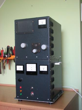
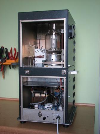
The power supply of the first grid is also a full wave one + stabilizer with Zener diode: -300V voltage of clogging the lamp and -200V initial operating point (anode current of 100mA). The power supply of the second grid is voltage doubler + stabilizer with a chain of Zener diodes and a high voltage transistor: 800V – a simple system, but demanding the selection of the transistor and not exceeding its SOAR. There is also 24V power supply for automatics and ventilator, which operates in three positions: off, active only when transmitting and turned off. Voltages for those power supplies are taken from one toroidal transformer. A total of 5 different voltages and 3 transformers – this is the cost of using the pentode. In fact, the whole complicated electronics is in the power supplies, the rest is mechanics. The amplifier is placed in a “tower” housing, in the bottom there are power supplies + automatics, input circuits, and in the top – a tube with a “pi” filter.
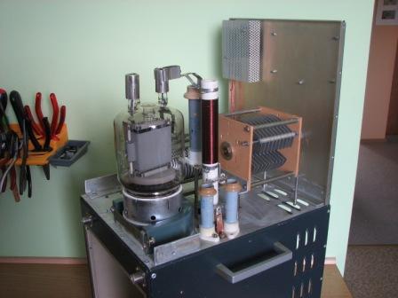


Ultimately, it will work on 14, 18, 21, 25MHz with 500W of power, 10-20W from a driver is enough to control it. The control signal power is deposited on non-inductive resistor, so only high frequency voltage goes to the first grid. The input filter adjusts the driver output (50ohm) to the amplifier input on different bands, what provides a good power transition and suppresses harmonics. The anode voltage is fed through the anode reactor, which is made on a ceramics bonded from the two bodies from the power wire resistors. There is control on the measures: anode voltage/current, grid current ½ and antenna current. The amplifier is initially tuned 10W for maximum antenna current measure indications and then only corrected on 20W. During the operation, the amplifier gives a lot of light and heat. At 20W of control and easy work, there is no need to turn on the ventilator – natural convection is enough. It weights 35kg.
Link to original thread – Wzmacniacz mocy KF na GU 81