Vermes
Advanced Member level 4
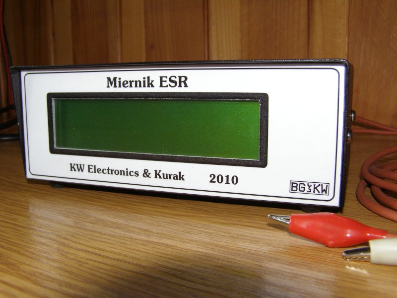
Description of this device was taken from:
Miernik ESR i mikrokontroler -ale jaki?
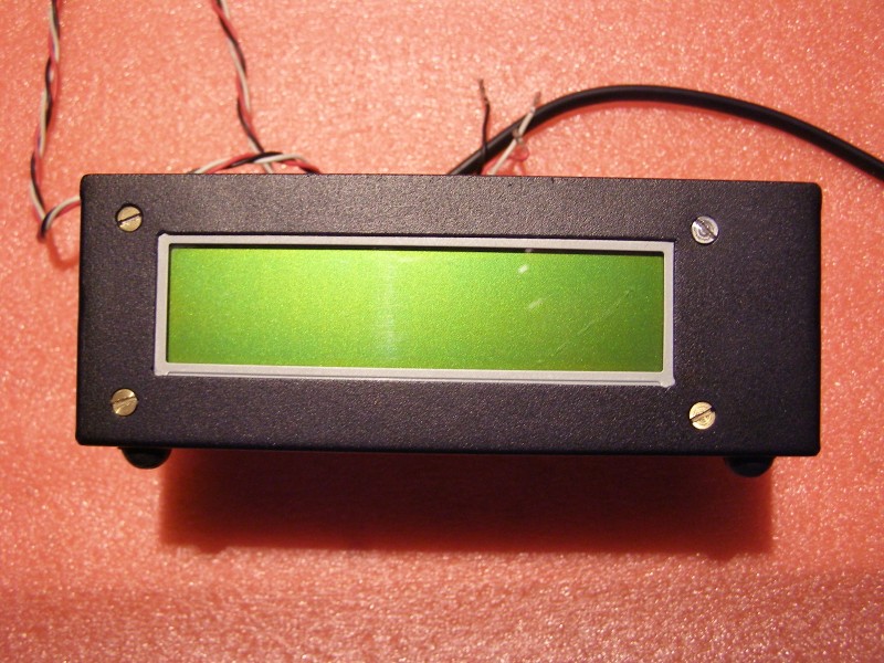
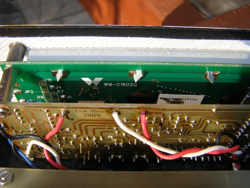
The PCB and the housing were made, so the device looks aesthetic. Microcontroller PIC 16F873A was used for the housing of the prototype. The display WM-C1602Q was taken from an old cash register. Similar displays are produced by Artronic, such as:
**broken link removed**
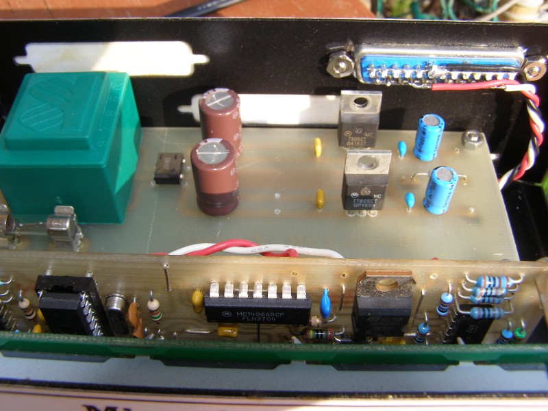
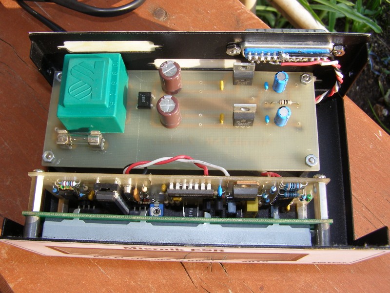
LCD type may be arbitrary, but it must have 2x16 characters and a driver compatible with HD4478. One of the assumptions was that the boards of the meter and display have the same size. That is why symmetrical power supply +5V and -5V was applied. It is a typical application of systems 7805 and 7905. Important thing is to use precision resistors in the measurement tracks, what increases the stability of the instrument. Similarly the potentiometer marked on the diagram as the R4, so called “helitrim” should be used. Resistors with a tolerance of 1% were used in this device, and on the board there is a place for the right potentiometer R4. In case of difficulties in obtaining the capacitor of 4,3nF, 4,7nF is also okay. Another thing to consider is the backlight of the display. It is realized from -5V. Path of the cathode of backlight should be cut off. It is shown in the following picture (marked with a red circle).
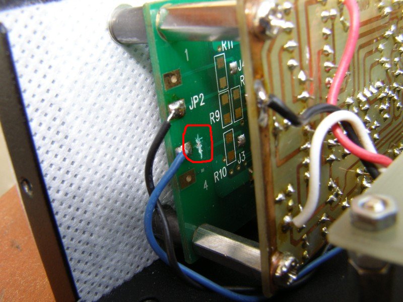
The current of the backlight was set on about 70mA, what gives a satisfactory, not too bright light.
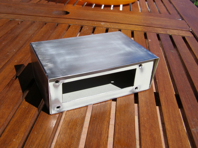
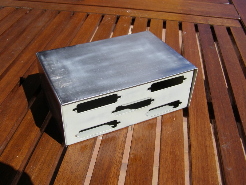
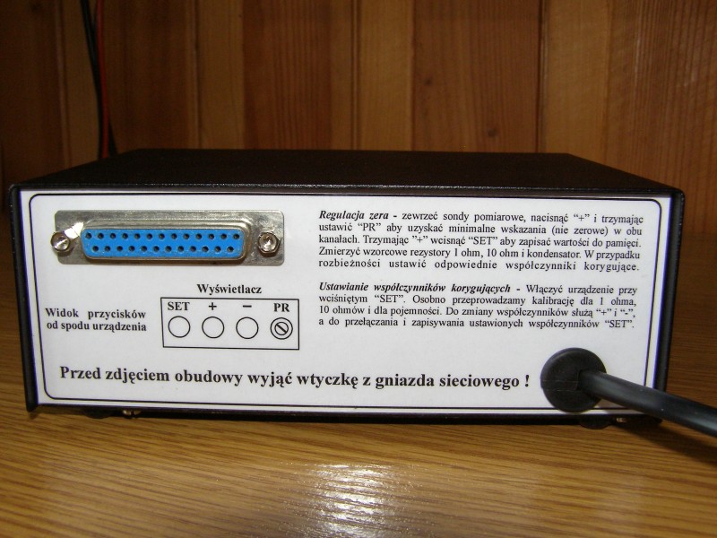
The board was made by photochemical method, and after soldering the path, protected with rosin solution in acetone. The whole was placed in a housing from an old printers switch, which was previously painted black with black matt powder. On the back side there is a brief instruction of the instrument calibration and DB25 socket (one of the existing holes was used), to which probes were plugged in the form of alligators. The measurement is done 4-wire, so the measuring cables connect on the alligators.
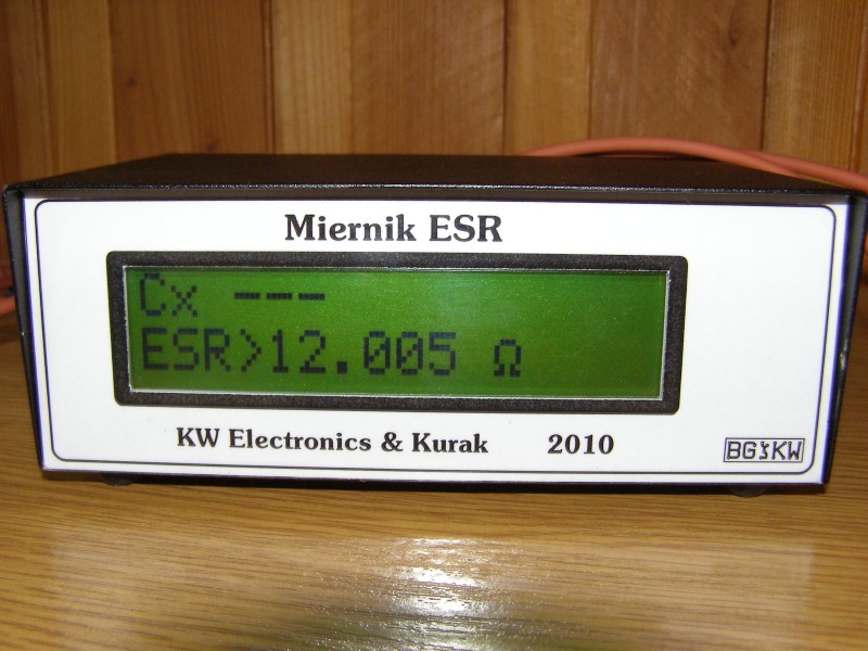
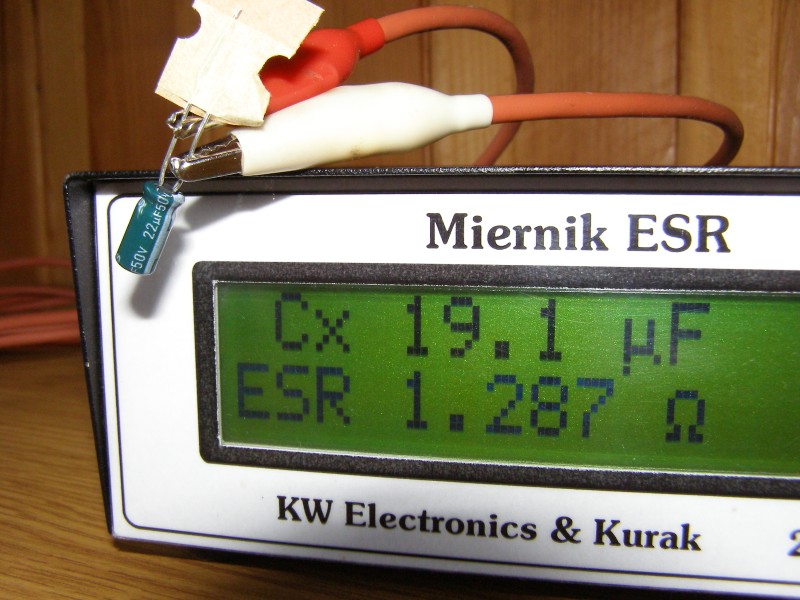
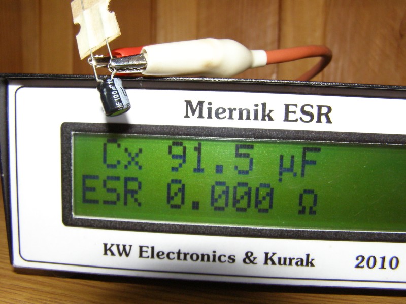
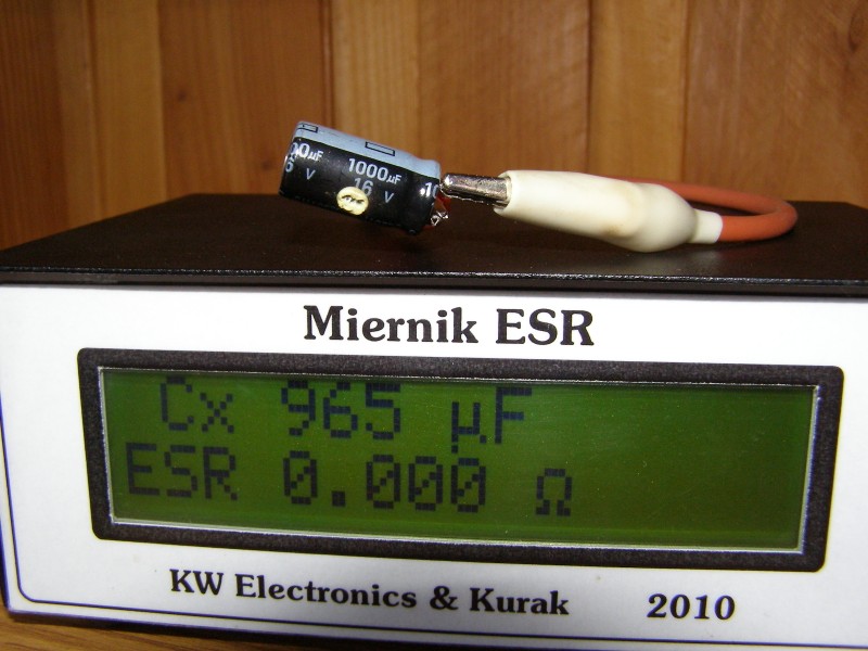
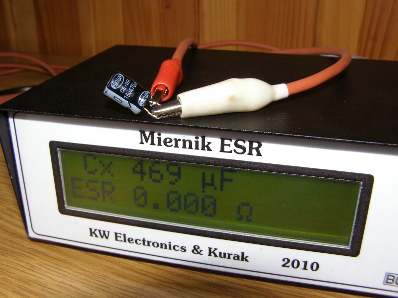
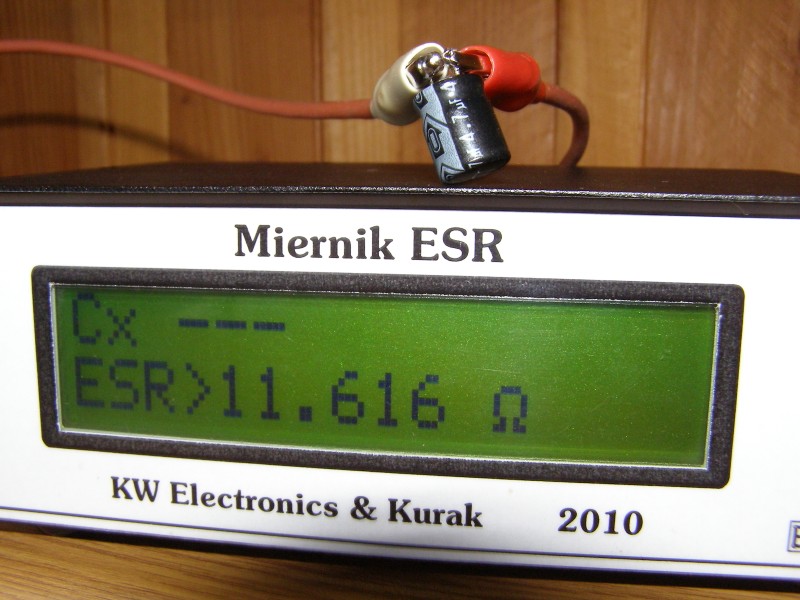
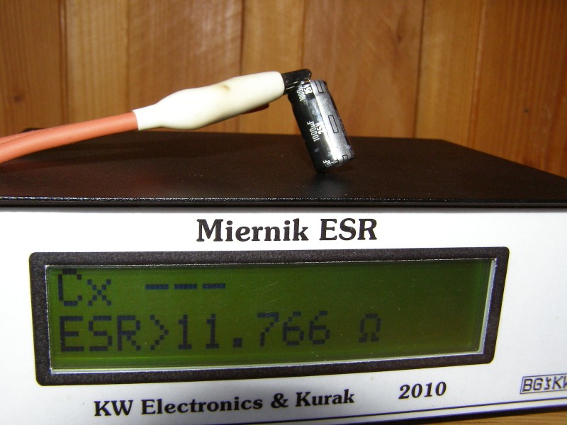
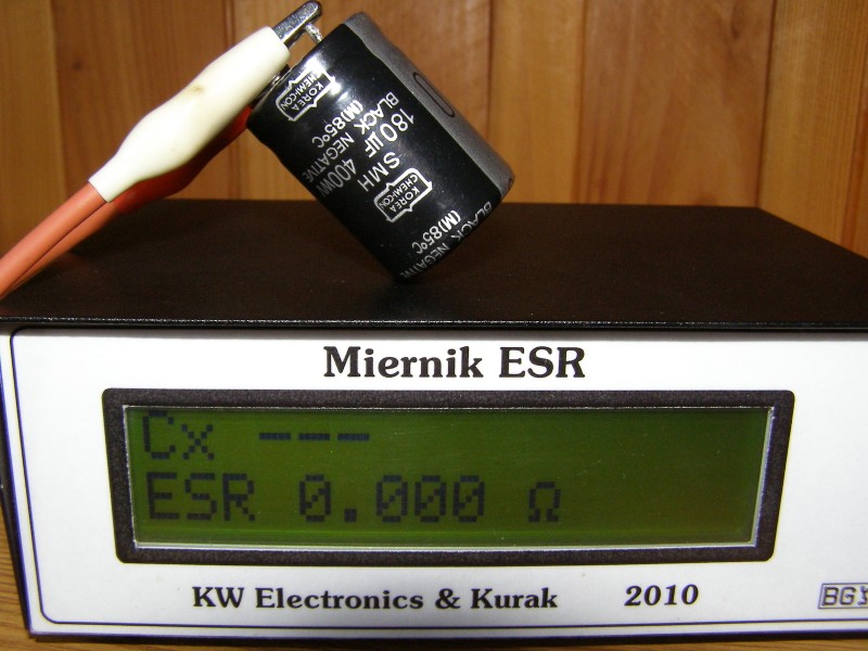
The capacitance is displayed in the top row, while in the lower one – ESR value. When there is no capacitors connected to the measurement, dashes are displayed in the top row, and in the lower one – ESR value greater than a specified value. In this case, “ESR > 12.005” is displayed. When the capacitor is efficient, its displayed capacity corresponds to its nominal capacity and ESR value is close to zero. In the event of loss of capacity by the capacitor or increasing the resistance ESR, it will be shown on the display accordingly. In this way, faulty electrolyte capacitor in a damaged device can be detected.
Attention! Both capacitors with small capacitance and capacitors to high voltage operation have a higher ESR than others and then only experience of user decides about the damage. Similarly, capacitors of smaller size have a higher ESR.
Below there are a few photos of measurement of working and damaged electrolyte capacitors.
Link to original thread (attachment) – Miernik wartości ESR kondensatorów elektrolitycznych