Continue to Site

Welcome to EDAboard.com

Welcome to our site! EDAboard.com is an international Electronics Discussion Forum focused on EDA software, circuits, schematics, books, theory, papers, asic, pld, 8051, DSP, Network, RF, Analog Design, PCB, Service Manuals... and a whole lot more! To participate you need to register. Registration is free. Click here to register now.

Small and cost effective connection

Status
Not open for further replies.

KPE

Newbie level 4
Joined
Aug 16, 2011
Messages
5
Helped
0
Reputation
0
Reaction score
0
Trophy points
1,281
Activity points
1,336
I'm looking for some ideas on how to connect two boards in a small and cost effective connection. I will use a programmer board to flash two devices on a small 1x1 inch board, and the small board needs some form of connection for this one time flash procedure. I will have to program 1000+ boards, so I will need something that is hopefully cheap on the small boards. I've been looking into FFC cables/connectors, and also wonder it could be done with test clips or pogo pins. But I don't know what common practices there is, as I'm quite new in the electronics business. These are my first boards ever made, so I'm not sure what my options are.
The space I have left on the board is around 7x14 mm and I will need 10 wires. The bottom plane is occupied by a battery, so there's not room for through hole connectors.
 

The lowest cost solution would be spring loaded test pins making contact with surface mount pads - it will add no cost to the board itself. You need to make a decent jig to hold the board and test pins and ensure everything is held in the correct place.
Keith

---------- Post added at 04:46 ---------- Previous post was at 04:44 ----------

By the way, you could also flash the devices before assembly with a ZIF socket, but that assumes there is no on board calibration to be done.
 

Thanks Keith. I will make a footprint for a spring loaded connector kind of solution, and the idea of flashing the devices before assembly might also come in handy. Actually a combination of these would be perfect I think. The chip is also available in OTP, but I'm a little scared of producing a lot of boards without beeing able to flash them later on. A mistake could quickly become very troublesome and costly.

Thanks for answering the question, I feel confident now.
 

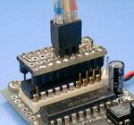
There is a very interesting solution using pin headers to "bite" the IC pins assuming that you are using dip package,
it is shown ELM - AVR programmer

attachment.php


Alex
 

Attachments

  • isp_clp.jpeg
    isp_clp.jpeg
    12.4 KB · Views: 153

Thanks for the link Alex. Yes I've seen quite a few test clips for DIP and SOIC, but the packages I use are QFN24 and LGA12, which are only 4x4 and 3x3 mm. I've been looking for test clips for these packages, but I didn't find any - which I actually didn't quite expect either, as the size is so small and the pins are almost invisible. I did find a socket for the QFN24, and the size is several times bigger than the package (see link below). I've also thought about using a dummy DIP or SOIC package, just to have a place where I could fix one of the normal/large test clips.

Anyway, I followed Keith's idea and found some spring loaded connectors from Samtec: Samtec | high speed, rugged / power, micro interconnects
And this test socket for QFN24: QFN24 test socket programming adapter QFN-24B-0.5-01

Thanks for your input though, I think I will read a little more about the USB to SPI bridge that they mention.
 

Special connectors like the said Samtec type can work. I guess Keith was rather referring to individual test pins that are used in in-circuit test. They allow a free arrangements of test pads and aren't limited to a particular form factor, except for a minimal pin distance depending on the type.

When you design your board for in-circuit programming, you have to assure, that the applied programming waveforms are tolerated by the other circuit and e.g. not shorted or distorted.
 

Ah yes - I see. Actually I had some space left on the board so I have now fitted in the footprint of one of the Samtec connectors and made all the traces to the pads. I think I will build in some protection on the programmer board. What is the best way to assure that in- and outputs are not shorted. Can I simply place a 1Mohm resitor in serial with each of the I/O's?
I think it should be ok for the high levels, but what about low levels and how much current will I need to counteract the internal pull-up resistors on the chips that receive programming?
Is this something that you normally examine in details, or is the impedance on low current chips extremely high so it's a common practise to just use a large resistor?

/Kenneth
 

Kenneth,

Yes, I was meaning the "bed-of-nails" type of spring loaded test probe so there would be no extra cost on the PCB, just some small test pads.

Normally you cannot add any series resistors to JTAG programming pins - check the chip manufacturer's data for exactly what you should and shouldn't do. If there is any series resistor allowed it is more likely to be something like 100 ohms, not 1M!

Keith.
 

Status
Not open for further replies.

Part and Inventory Search

Welcome to EDABoard.com

Sponsor

Back
Top