Vermes
Advanced Member level 4
How it works
The principle of measurement of oxygen saturation is based on the fact, that oxygenated blood (specifically hemoglobin) absorbs differently each wavelength. In short, screen finger by 660nm and 940nm light and on the basis of relative of the received signals amplitudes, calculate the parameter of interest. Heart rate is calculated on basis of the time interval between peaks on the pletysmographic curve.
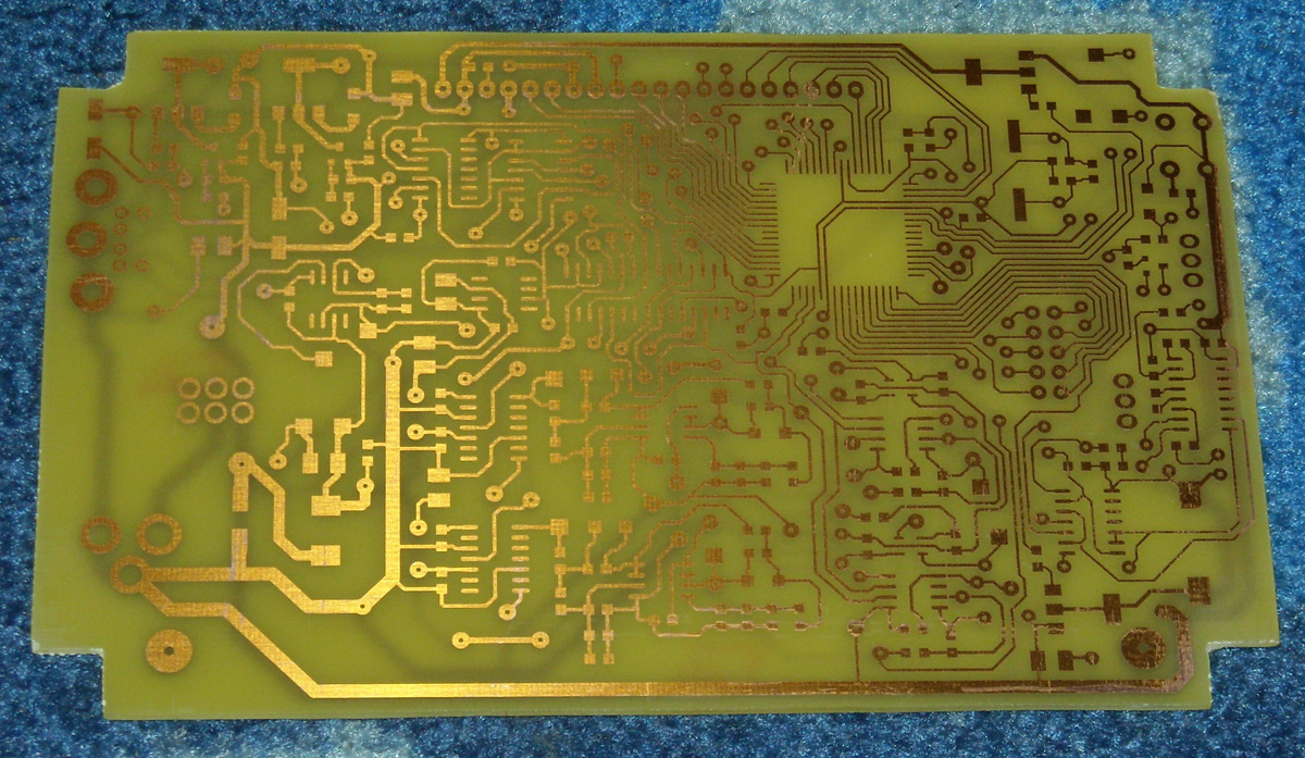
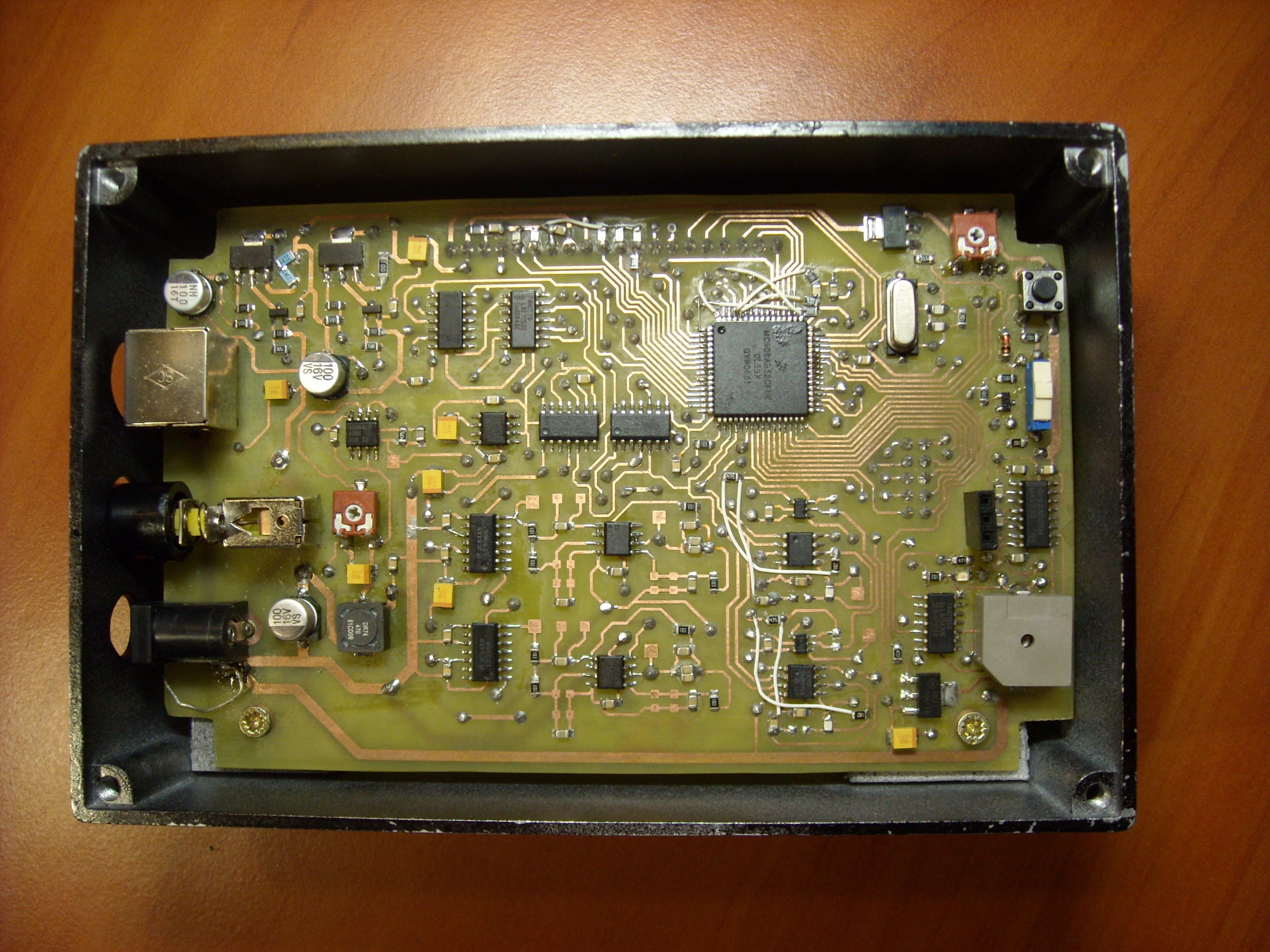
Main plate
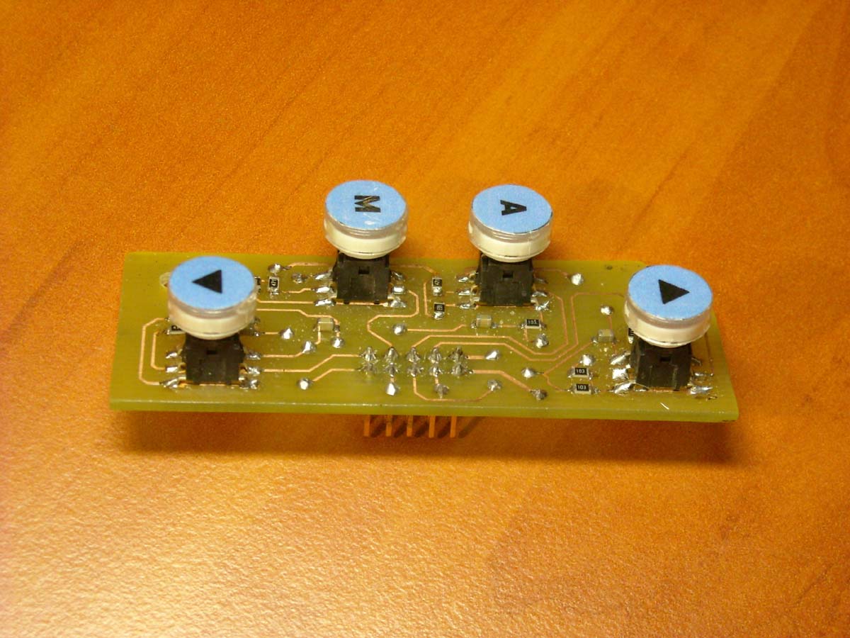
The system is driven by a microcontroller 68HC908AB32. Waveforms of 4-output PWM by a small logic function, which controls S&H systems and bridge H activating alternately diodes. The lower transistors in the bridge with C/A transducers are regulated current source providing the brightness of light pulses. The signal from the photodetector is demultiplexed (red and infrared pulses go to different processing circuits), demodulated and filtered. Next, the signal goes to the amplifier with programmable gain, to finally be tested by the transmitter contained in the structure of the microcontroller. Data are presented on a graphical display 192x64 pixels. Keyboard was made on a separate plate by backlighted buttons with description glued. Those buttons are used to set the alarms (heart rate decrease/increase, decrease in oxygen saturation). The whole is powered from the 5V power supply. As shown in the photograph, minor corrections in the schema diagram were introduced after soldering the whole.
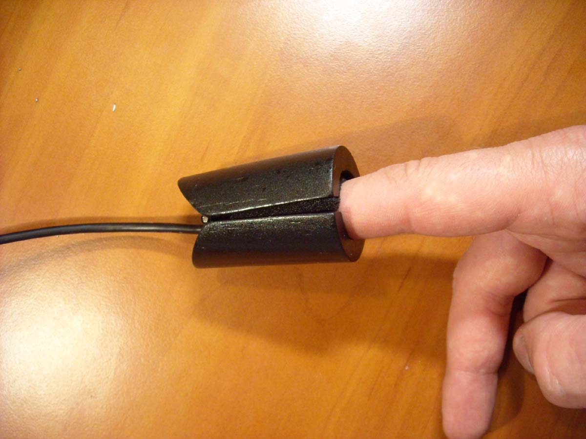
The sensor on the finger
Probe on the finger was made of oak shaft from the shovel. The wooden piece was cut in half, then drilled with the table drill. Hinge visible on the photograph was formed with a piece of large brass wing hinge. Spring was taken from hair pin type “jaws with teeth”. Cable was taken from keyboard Logitech UltraX. There are 4 LEDs at the top of the sensor. 2 of them are red and 2 infrared connected antiparallel. At the bottom of the sensor, there is PIN photodiode located. Additionally, a piece of sponge was mounted in the sensor. It makes the sensor securely holds in both thin and thick fingers.
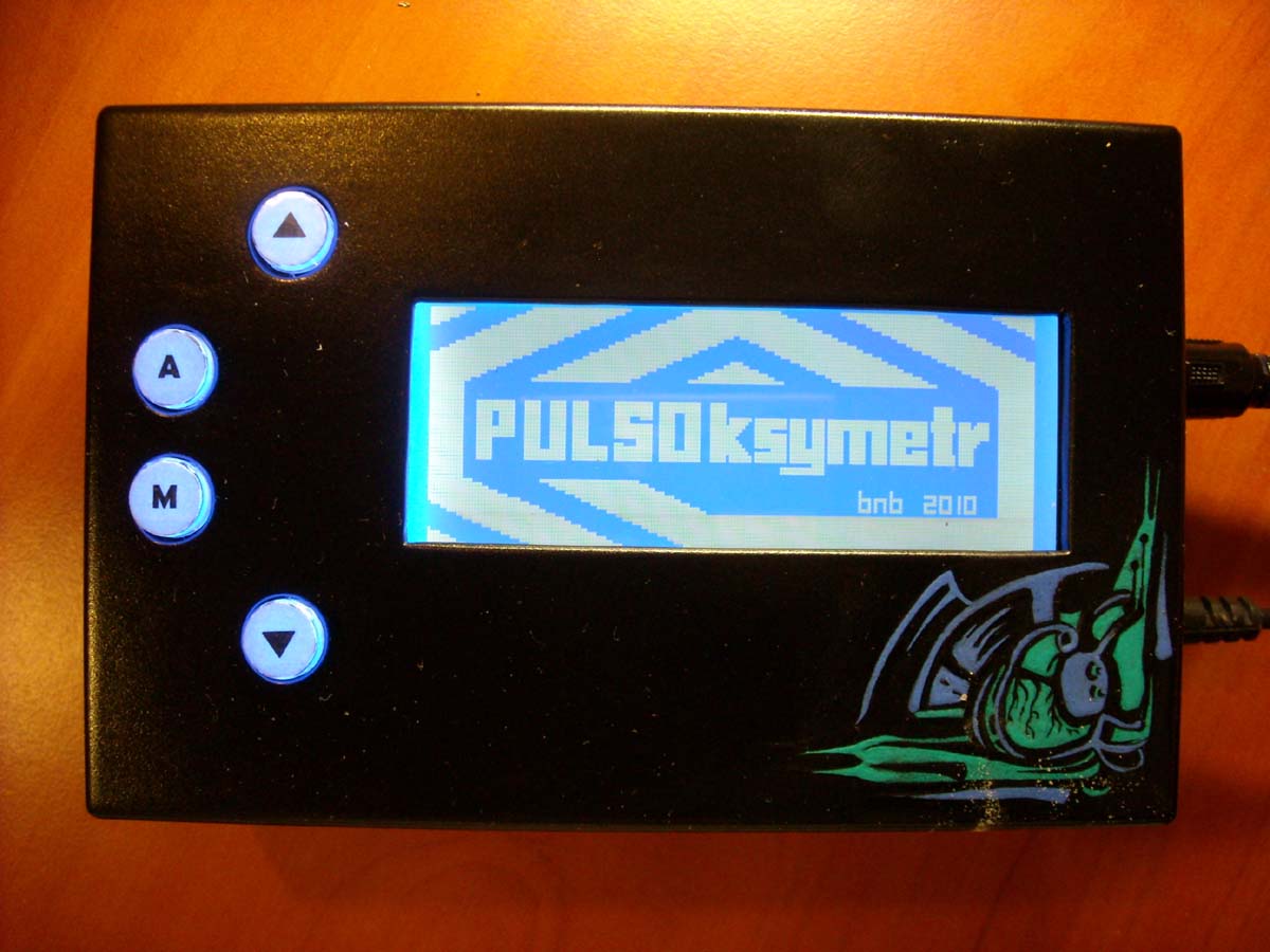
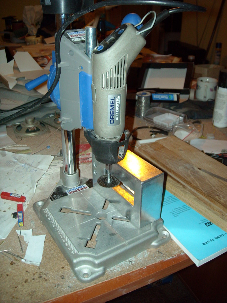
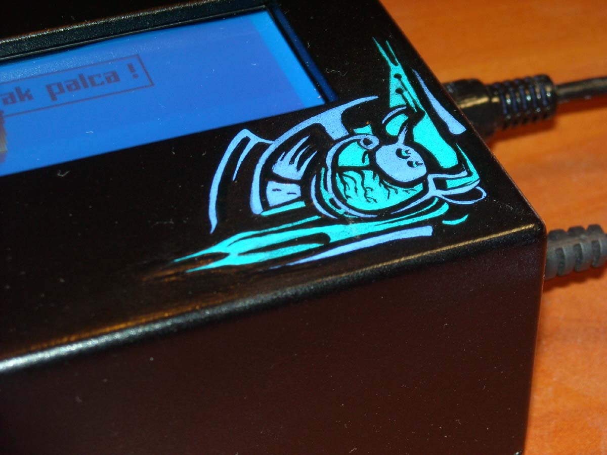
Housing
The housing was made of an aluminum can. A window was cut with dremel mounted in a rack. The whole was painted black semi-gloss with spray. At the end, graphics was applied.

Below, there are some additional photos and a video of the device working.


Link to original thread (attachment) – Pulsoksymetr: pomiar tętna i nasycenia krwi tętniczej tlenem