Vermes
Advanced Member level 4

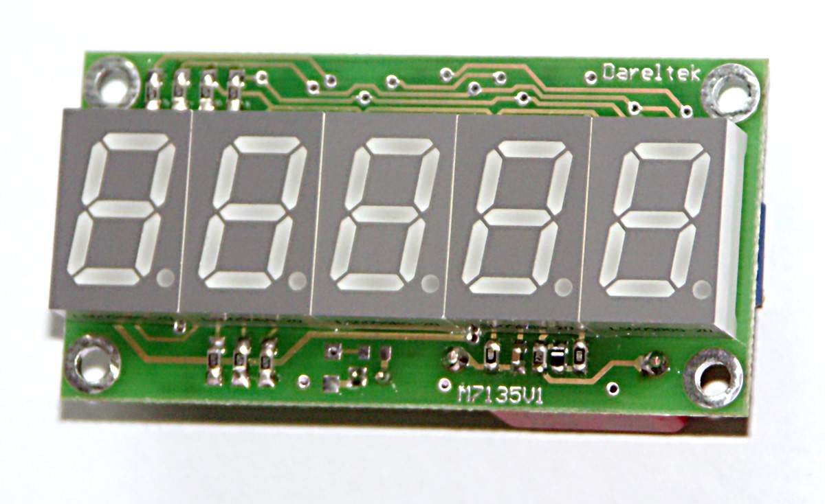
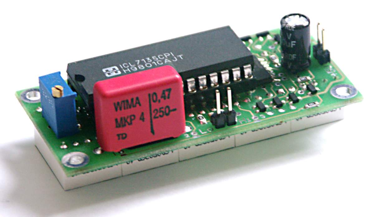
Everything fit the plate 33mm x 66mm and the depth of module is less than 24mm. 5 displays 14,22mm, but it is not necessary to solder the left digit, losing the ability to display values above 10000 and the minus sign, what in most cases is acceptable. This digit has the function of muting the zero and if the voltage does not exceed the value of “9999” it is off. To build the meter, except ICL7135, CD4543 for decoding the numbers BCD, 74HC14 for the generator and the multiplier, TL431C as a reference source (17ppm typical) were used. Strengthening the current for the displays was done on transistors, because using drivers required a larger area of the plate. Polypropylene capacitor was applied in integrator, in this application it is necessary. The use of MKT makes class ICL7107 from this meter.
The basic sensitivity of this meter is 1,9999V, you can get additional ranges 19,999V and 199,99V with a divider, and 1999,9V only with external high-voltage resistor. There is also access to the HOLD function and other signals present in the chip.
While designing the scheme, there were two main assumptions:
- no expensive items
- the least items
BCD decoder was made on 4543, it displays the full 6 and 9 and can reverse the phase of the output signal, what is very much needed feature in this system. Strengthening the current for the displays was done on the transistors, they can be arranged in different places, making it easier to design a small plate. All the transistors are in common collector configuration, that can be done at 5V power supply. With this configuration the transistors switch faster (no saturation). One transistor had to be on a common emitter, it turns on number one on the left, and when it is zero, the display is blank.
TL431C was used as reference voltage. Change of the temperature by 10 degrees Celsius would change indications of the meter by 3 for full scale 19999, at measurement of 50V (meter 200V) indication may not change then.


Link to original thread (attachment) – Woltomierz panelowy 4 1/2 cyfry na ICL7135