Vermes
Advanced Member level 4
Projector consists of three laser modules: red (650nm), green (532nm) and violet (405nm). Light beam emitted by these lasers are combined by interference filters, also called dichroic mirrors or just “dichro”. The principle of those filters operation is similar to the principle of Fabry-Perot interferometer operation. The effect is that light of a given wavelength (or a band) is very well reflected, while others are very well passed (or vice versa). Those filters have to be very precisely aligned at right angles, so that the light beam can best overlap. For convenient adjustment of this type of optics, special handles are used. They are called Kinematic Mount. Fabric handles are very expensive, but they can be self made, like it is shown in the pictures below:
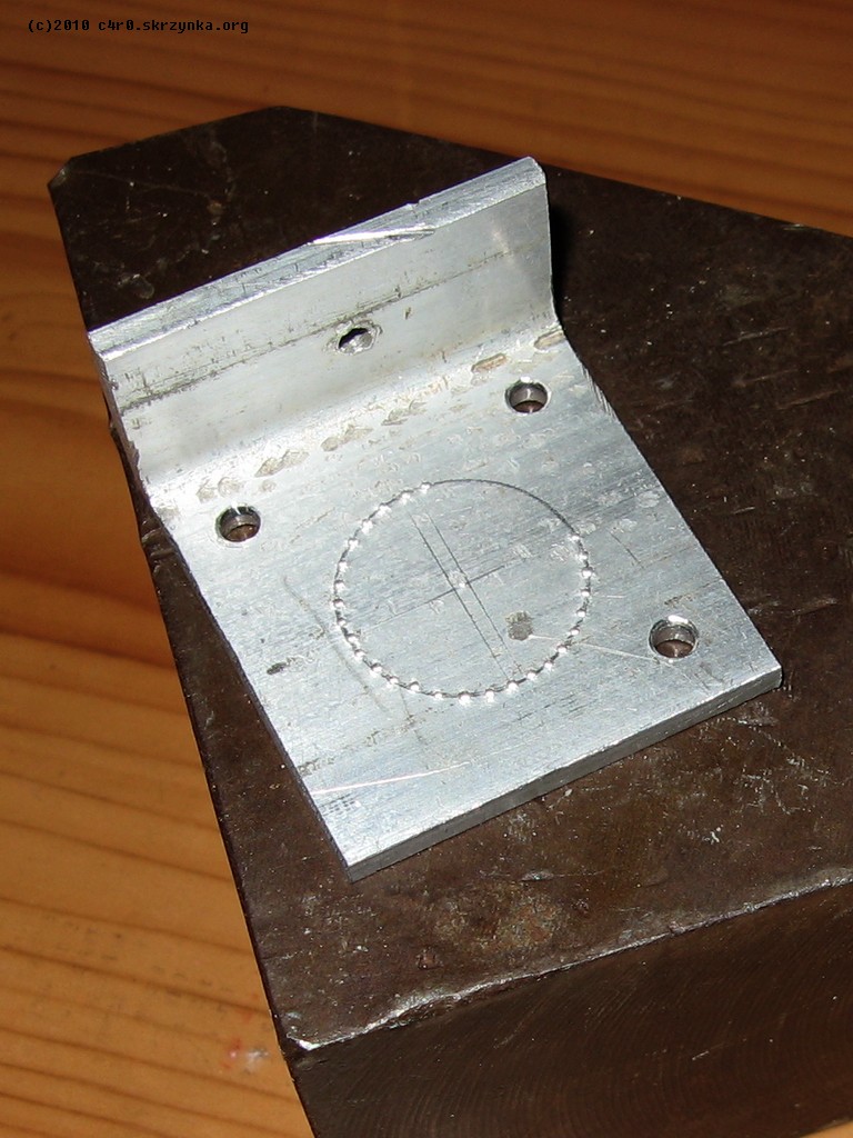
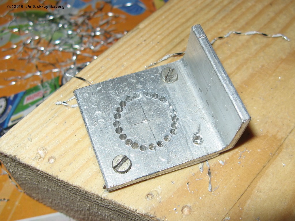
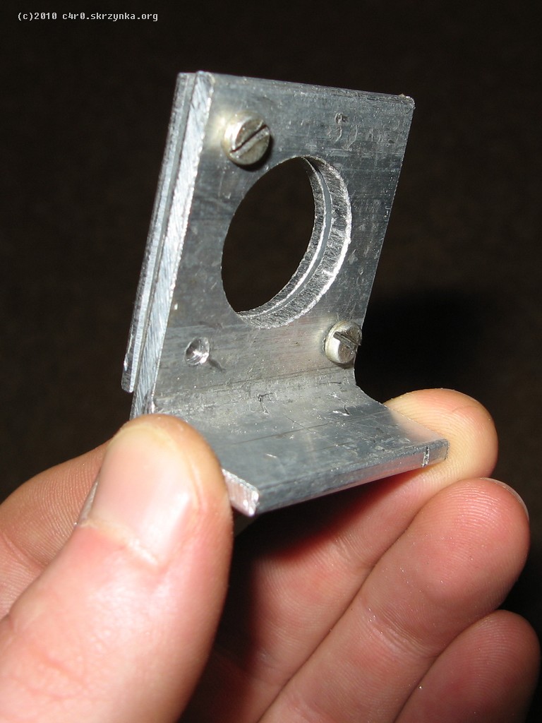

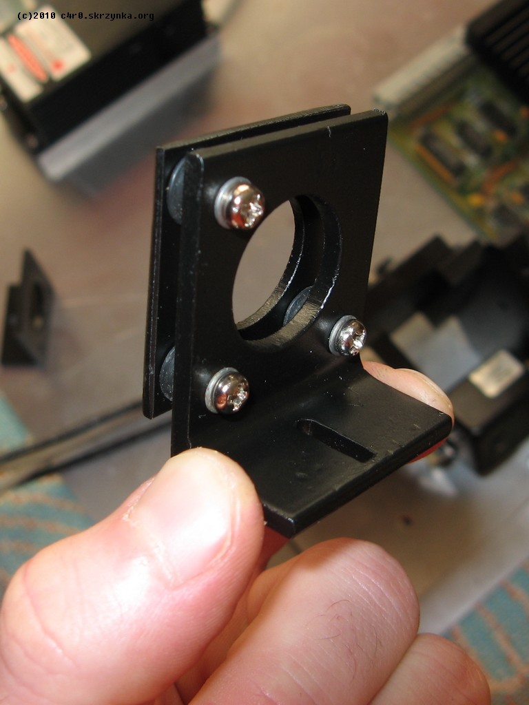
Such handle allows precise adjustment of the angle separately in vertical and horizontal axis, by means of two screws. Three handles are needed to make described structures: two for dichro filters and one for the mirror.
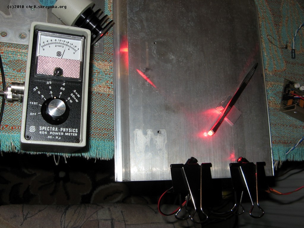
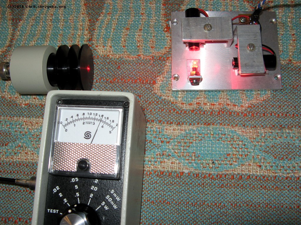
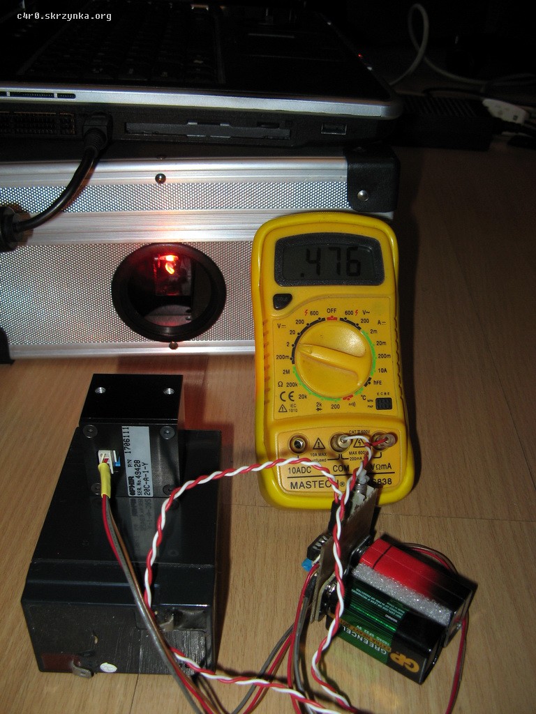
The red module consists of two laser diodes 650nm from DVD burners, working at current of about 350mA. Each diode is mounted in the housing of low-power laser module, which contains an acrylic lens. These modules are mounted on an aluminum block and the light beam generated by them are connected into one by using a polarizing beamsplitter, also taken off from the DVD burner. The beamsplitter reflects light of e.g. vertical linear polarization, and passes the light of horizontal polarization (which is orthogonal to the vertical one). Laser diodes emit polarized light, so when one of them is mounted turned 90 degrees in relation to the other, they give two beams of opposite polarization, which can be connected that way. The total power of light emitted by this double red laser is about 350mW, what can be seen on one of the following pictures. At the current, which is set to operate the projector, the power of this laser is approximately 300mW.
The green laser is Chinese laser module DPSS with second harmonic generation, power 100mW. It was taken off a broken disco laser.
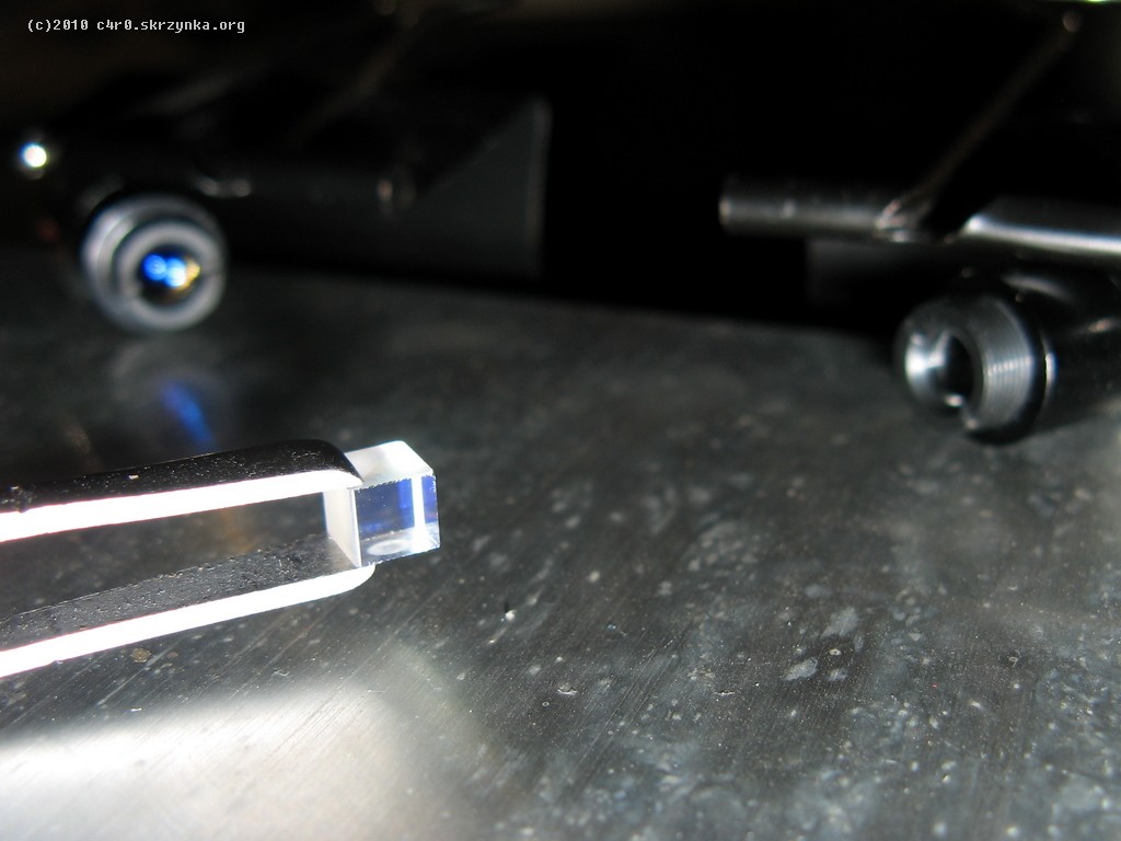
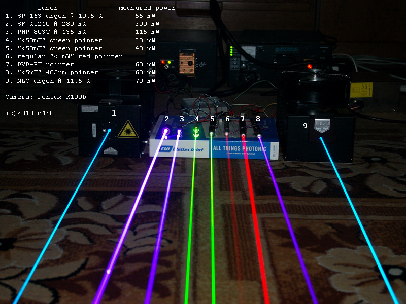
The violet laser is laser diode 405nm from BlyRay reader (laser module SF-AW210). Those diodes may give more than 300mW of optic power, but at this load they do not work long. In this project, the diode is powered by 270mA, which gives less than 300mW. Used module is shown on the following picture (number 2).
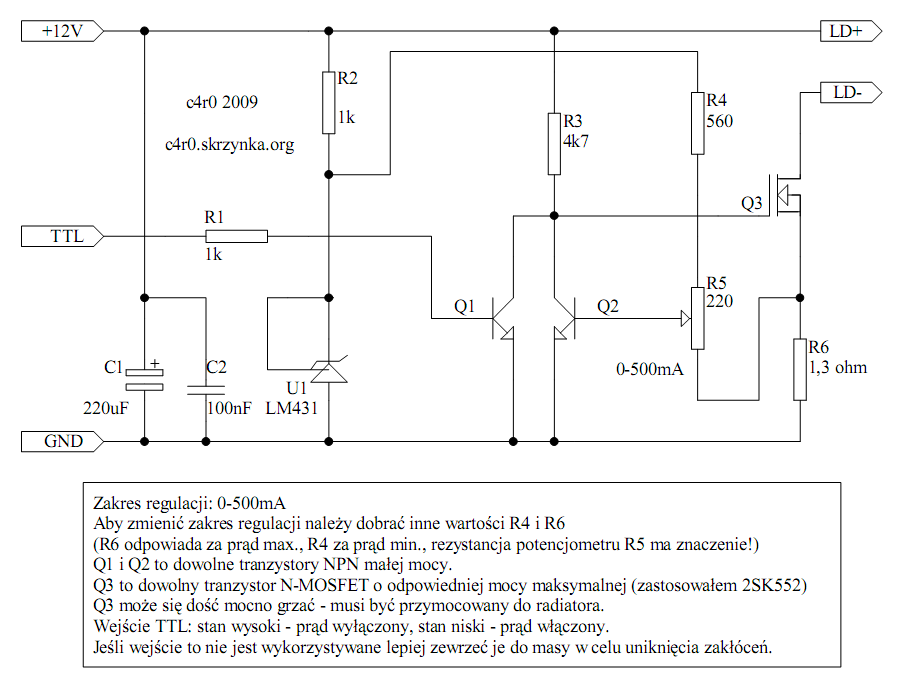
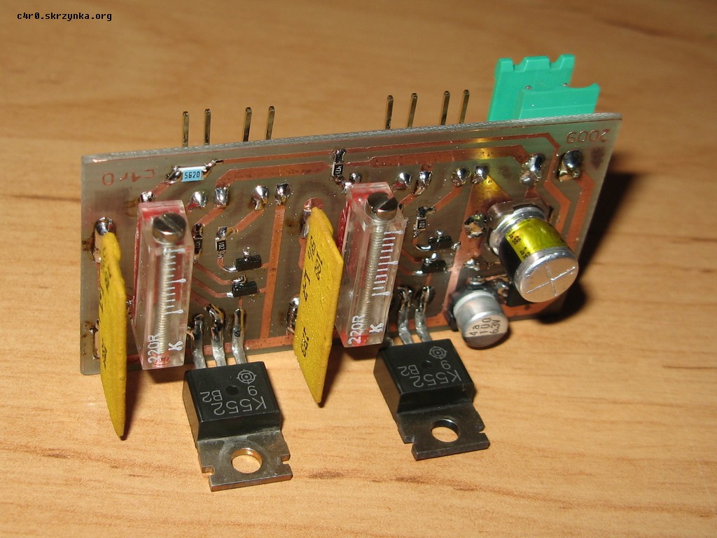
To power red and violet laser (the green one has its own fabric power supply), impulse power supply was used, taken off HP printer and drivers stabilizing the current. Below there is schema and picture of this system:
Of course laser powers have to be properly chosen, that after activating they give white light. The human eye is not equally sensitive to all colors (see the function V (lambda)), which is why laser powers are not the same.
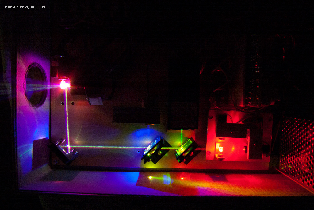
By three lasers and dichro filters, light beams RGB can be connected to gain white light. Scanning system to move light beam and draw is made of galvo scanners. It consists of two independent channels (X and Y deflection). Each channel has a scanner, which is built similar to analogue meter (with an indicator) – there is the axis with the magnet, a mirror mounted on it and the coils that swing the axis. Additionally, in order to work more precisely and faster, scanners are equipped with an optic position detector (photodiodes and movable shutter), which is plugged in a feedback loop of the signal amplifier. Unfortunately, the scanner is a mechanical element with inertia, resonance etc. That is why the amplifier to control it is not simple to make. A special regulator is needed, which is difficult to be self-made and to tune. That is why it is better to buy a new, tuned scanning set. The picture below shows a cheap Chinese one:
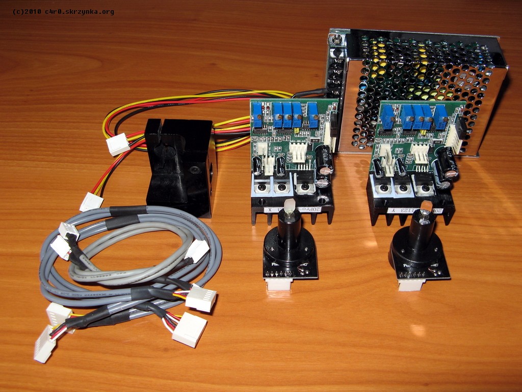
There are two scanners equipped with dielectric mirrors and tuned amplifiers and a handle for mounting the scanners. Also there is a impulse power supply. Each amplifier has a symmetric analogue input, at which a signal of the mirror deflection is given.
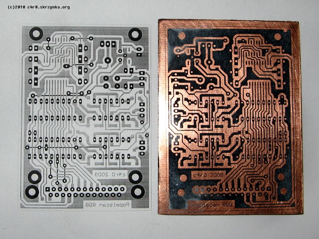
Interface providing analogue signals for controlling the scanning system and for turning on and off each lasers in right moments is an electronic part of the projector. The signals are sent via a cable in ILDA standard (where controlling the lasers is also analogue) – most laser projectors on the market have this type of input. There are few USB-ILDA interfaces, but they are expensive and available with a dedicated software for laser shows and have no documentation for own constructing. The simplest interface providing right signals – Popelscan is used. The interface uses LPT port of the computer (unfortunately, it is rare now). There are two 8-bit DACs on the plate, providing X and Y signals and TTL latch providing the binary signals on and off three lasers. The following schema and pictures show self made Popelscan:
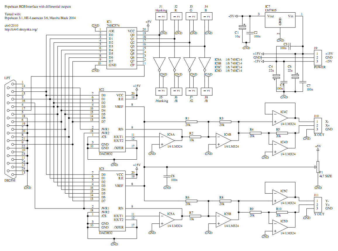


The interface is supported by few programs: original Popelscan (versions up to 3.1), HE-Laserscan, Mamba Black 2004 and NLS. The last one is free, quite fast and supports vector graphic files in ILDA standard (*.ILD), which are widely used during laser shows. Program NLS in version 1.6.7 can be downloaded HERE.
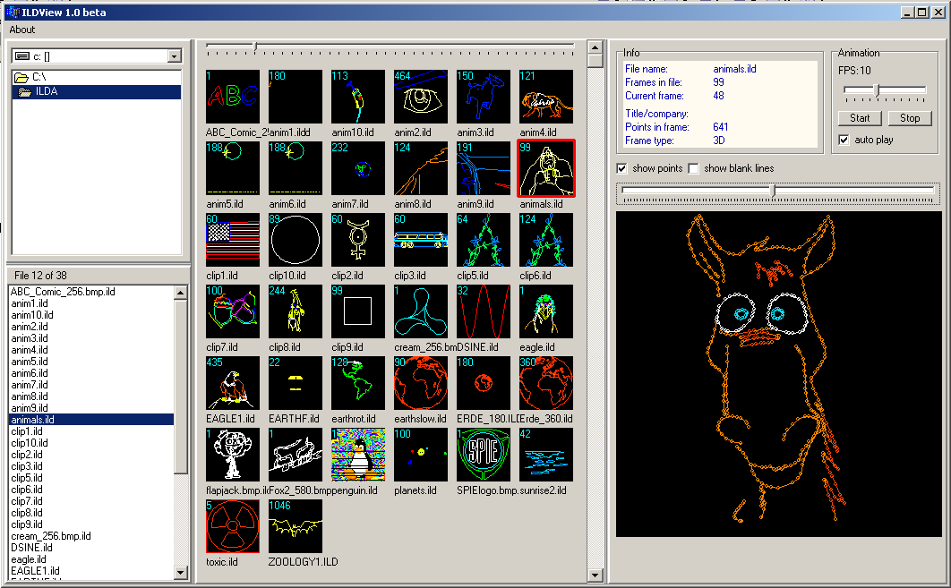
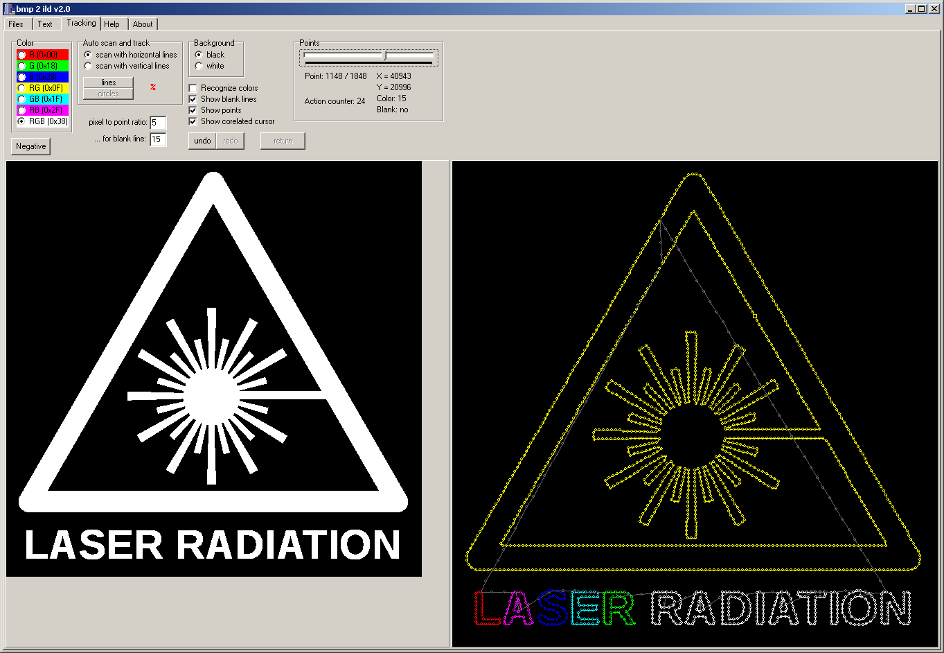
A program that allows to modify .BMP files to .ILD was self made, just like the browser for these files. Pictures below show the windows of these programs.
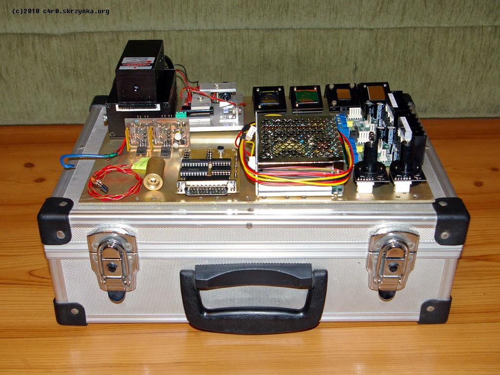
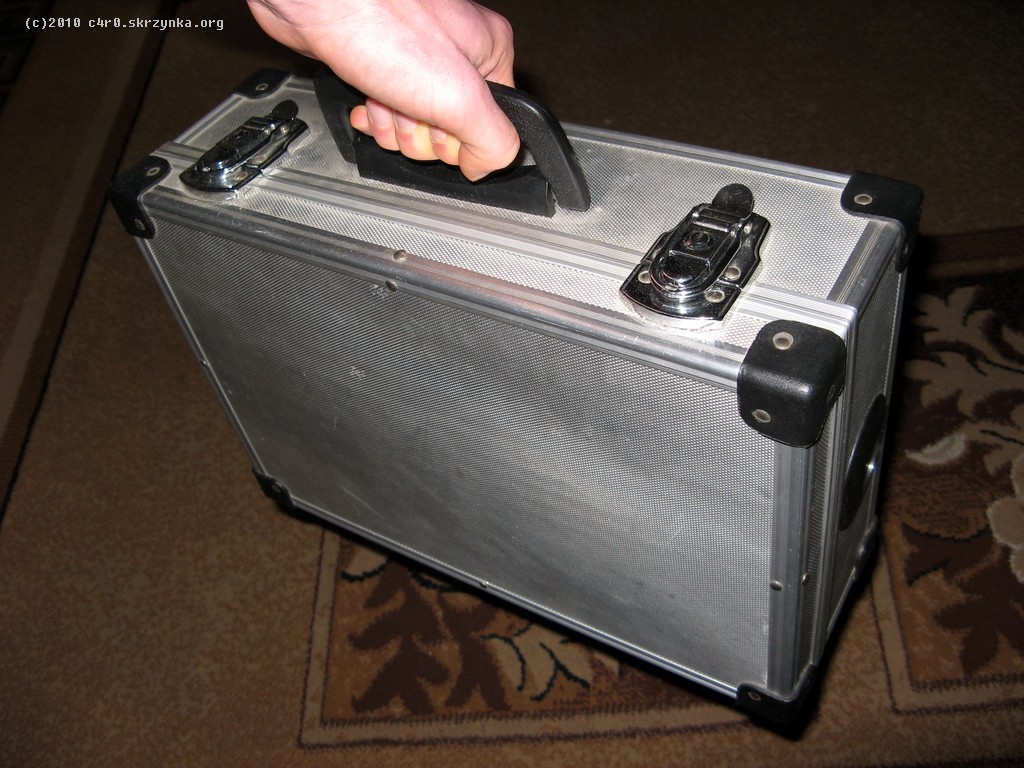
A suitcase made of beaver-board covered with aluminum foil was used as a housing. It is very comfortable to use. The following picture shows all parts of the projector gathered together.
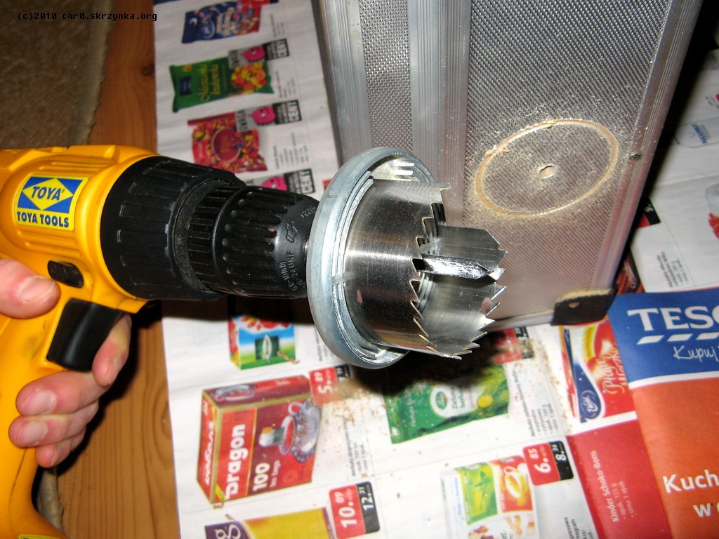
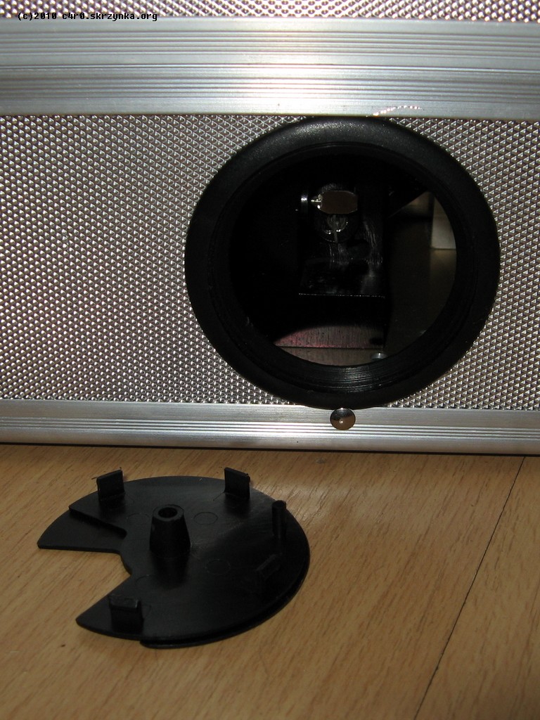
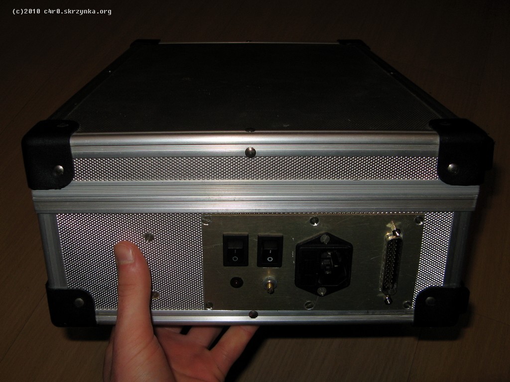
As a basis for mounting the optics and part of electronics, an aluminum plate 3mm, fitting to the suitcase was used. After planning allocation of individual elements, the corresponding threaded holes were made and everything was installed on the plate. Popelscan plate, along with switches, connectors, LED indicator light and a potentiometer to adjust the image size was fixed to a piece of the same aluminum plate, which was later mounted into the suitcase's wall, as shown in the pictures below. As a hole, by which light comes out, a conduit for furniture with a diameter of 60mm was used. It has a lid that is easy to put on and off, it looks well and is cheap, what makes it very good in this application.
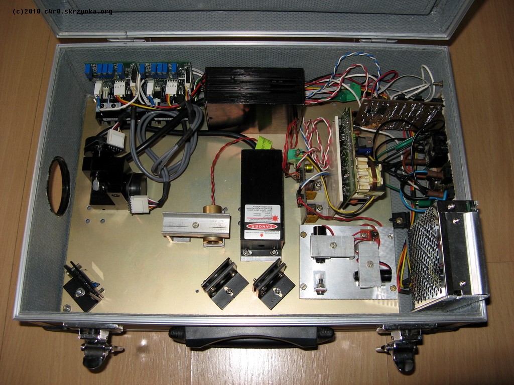
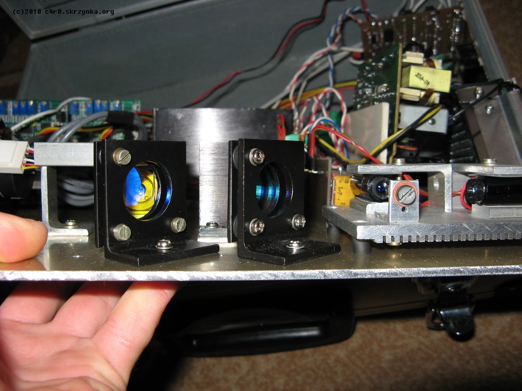

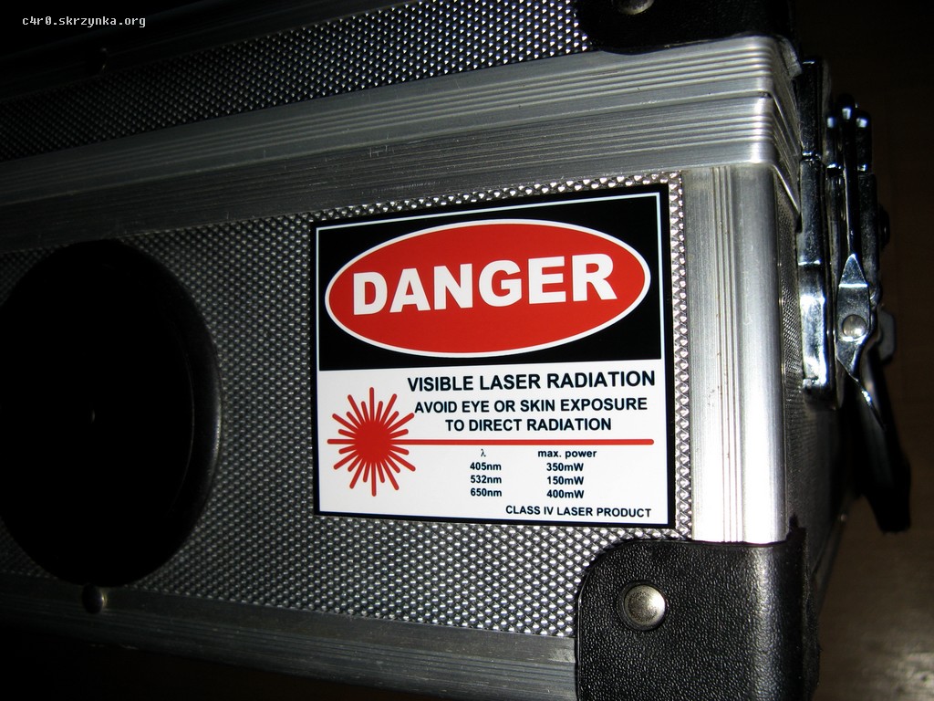
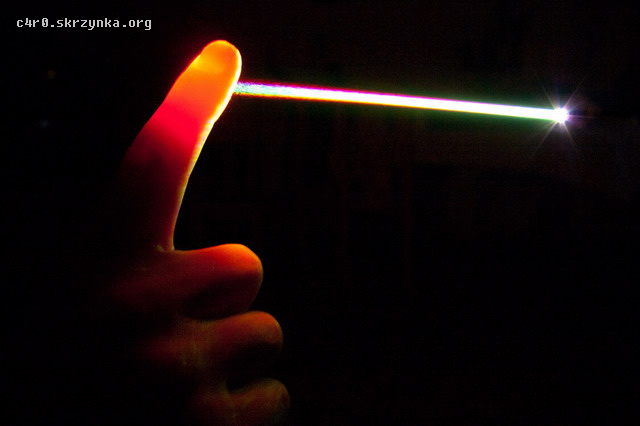
Below there are pictures of the construction. As it is shown on one of those pictures, the total power of light beam is almost 0,5W. The sum of individual lasers power is greater (300mW + 100mW 532nm + 405nm = about 700mW), but of course each optical element (two dichro filters and three mirrors) introduces its losses. This power is obviously very dangerous, so caution is essential. When all three lasers permanent on, the stationary laser beam burns a big hole in the carton and brews the skin.
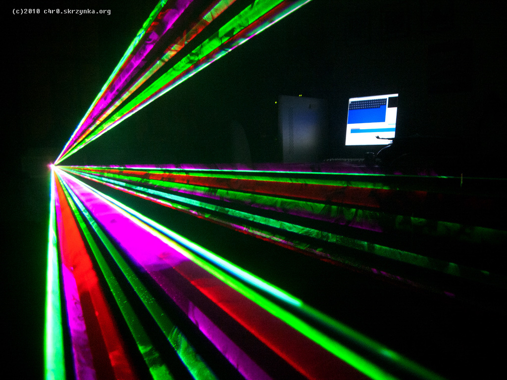
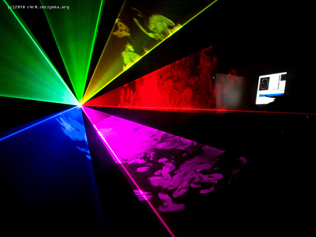
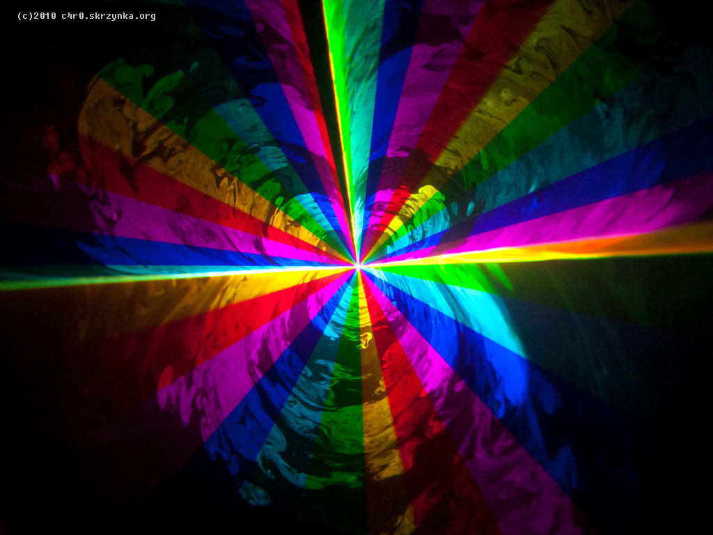
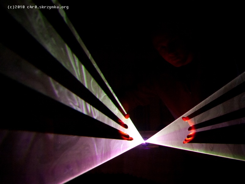
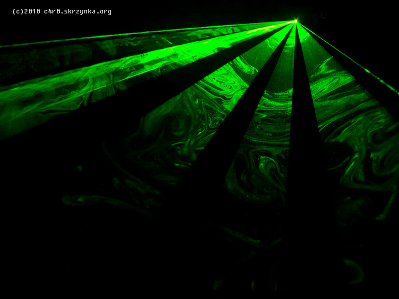
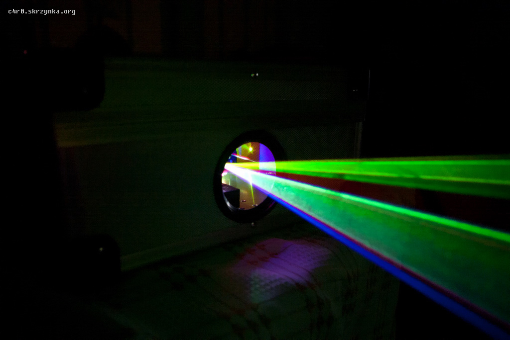
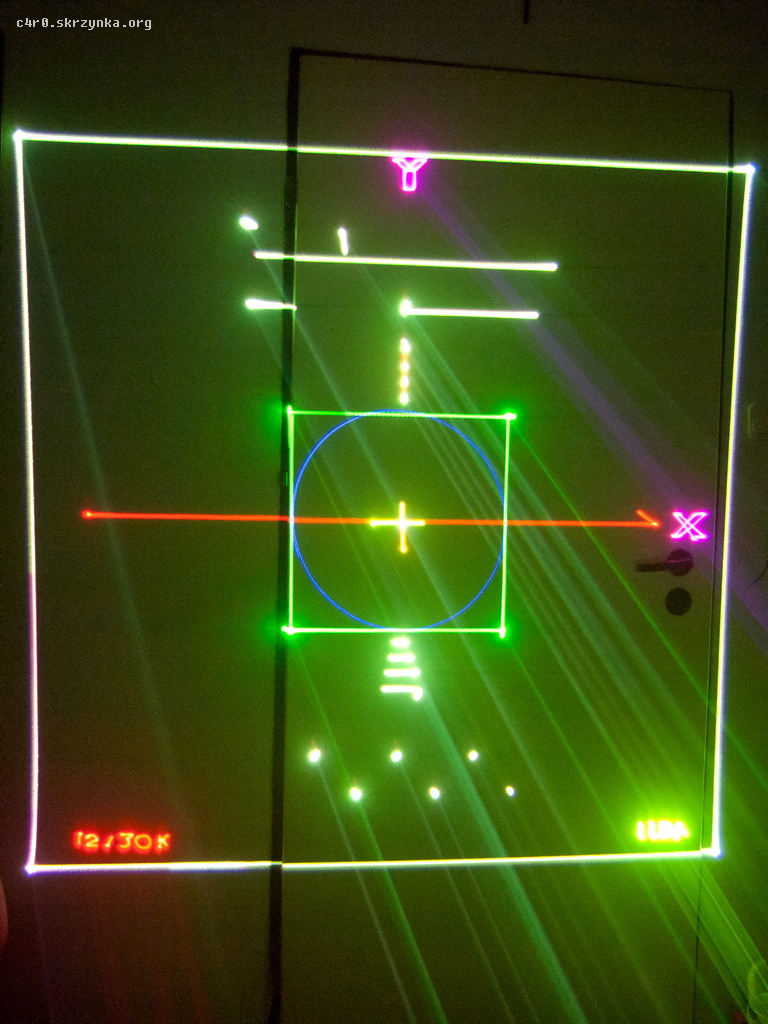
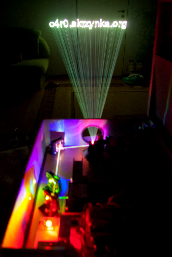
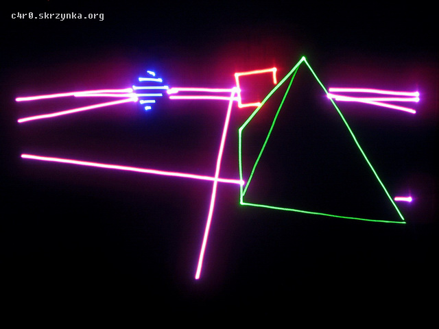
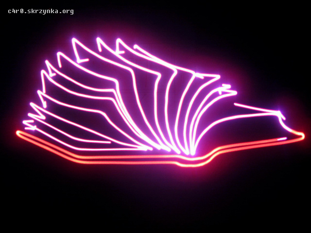
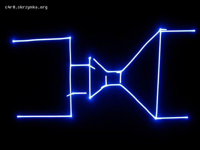
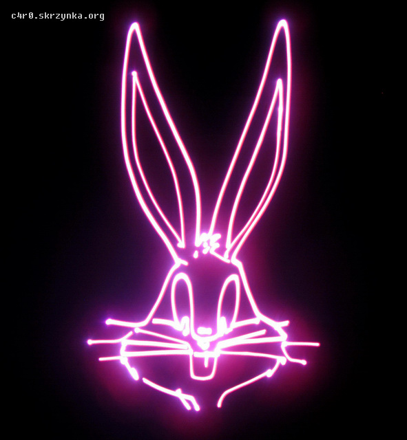
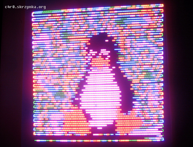
There are some pictures of the effects of the projector and two videos. First part was made in a smoky room. Smoke was made with glycerine from the pharmacy atomised by spray on a hot iron.


 **broken link removed**
Link to original thread (attachment) – Projektor laserowy RGB o mocy pół wata

 how to change into another one, like USB or COM ???