Continue to Site

Welcome to EDAboard.com

Welcome to our site! EDAboard.com is an international Electronics Discussion Forum focused on EDA software, circuits, schematics, books, theory, papers, asic, pld, 8051, DSP, Network, RF, Analog Design, PCB, Service Manuals... and a whole lot more! To participate you need to register. Registration is free. Click here to register now.

Understanding Circuit Schematics

Status
Not open for further replies.

rotary

Junior Member level 3
Joined
Oct 10, 2011
Messages
25
Helped
1
Reputation
2
Reaction score
1
Trophy points
1,283
Activity points
1,474
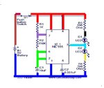
Can someone please tell me how to understand circuit schematics like the one below.
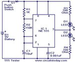
555-tester-circuit.JPG

It's not clear to me on this schematic whether D1 is connected from pin 3 then to R3 then R3 to positive , or whether D1 is connected from pin 3 then to R3 then R3 to pin 4 which is connected to positive. How am I supposed to know by looking at the schematic?

In other words are D1 and R3 connected to pin 4 or straight to positive? And how can i tell just by looking at the schematic?
 

Just look at the schematic and what you see is what it means.
Pin 3 is connected to D1.
D1 is connected to R3 at one end (and the other one going to pin 3 is also connected to D2).
The other end of R3 is connected to Positive of battery via a switch.
Pin 4, Pin 8 and one end of R1 is also connected to Positive of battery via the switch shown in the schematic.
Top most line, all points are on the positive supply.
Bottom most line, all points are on the negative of the supply.
LED D1 glows when Pin 3 goes low and
LED D2 glows when Pin 3 goes High.
It will be toggling between the two states approximately every second.
For timing calculations you may use the following interesting link giving ready made calculator.

555 Timer Calculator
 

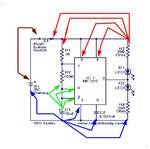
You can imagine that, this circuit has common points for components
like different colors in this picture

Circuit_points.jpg
 
So R3 isn't connected to pin 4 then. Can i tell that because there is no dot on the circuit where R3 connects to the positive rail? Is that how it works?
 

R3 is connected to pin 4
Normally circuit schematics do not use connect point mark (dot) in single wire corners.
 

So how am I supposed to know just by looking at the circuit that R3 is connected to pin 4 and not straight to positive?
 

Look my colored picture , between bright red and dark red is switch S1.
If you follow line from R3 it goes to IC-pin 4, IC-pin 8, R1 and S1 right pin. (Bright red)
S1 breaks to line to battery plus. S1 left pin goes to plus pin. (Dark red)
 

Is R4 connected to pin 5 ?

---------- Post added at 19:50 ---------- Previous post was at 19:46 ----------

Look my colored picture , between bright red and dark red is switch S1.
If you follow line from R3 it goes to IC-pin 4, IC-pin 8, R1 and S1 right pin. (Bright red)
S1 breaks to line to battery plus. S1 left pin goes to plus pin. (Dark red)

Yes but how can I tell by looking at the circuit that R3 is connected to pin 4? The schematics don't have colours drawn on to show what is connected to what.
 

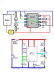
Everything on bright red is connected together.
Just follow the line , if there is crossing with dot , it is connected.

Circuit_points_2.jpg
 

How do I know what R4 is connected to? There is a crossing with a dot at pin 1 and pin 5, does this mean R4 is connected to pin1 and pin 5?
 

Start from R4 : 1. crossing to C2 : 2. crossing to IC pin 1 : 3. crossing to C1 : then corner to battery minus.
All these points are connected together. (Blue)
 

When you say connected together, do you mean they all go to ground but not directly to each other?
 

Yes, if you imagine that all blue colored is one connective point or ground point or battery minus point :
they all are connected there and together.
Drawn lines and dots only show , which wires and pins of the components are connected together ( solder points).
 

Ok, so R3 is connected to pin 4 directly? Does that mean R4 is connected to pin 5 directly since the connections look identical to each other on the schematic.
 

R3 is connected to pin 4 directly? >> Yes
Look schematic : R4 is connected to pin 1 directly .
Pin 5 is connected to capacitor C2 upper wire and C2 lower wire is connected to all blue wires.

You should think , that colored wires are copper foils in printed circuit board, where components are soldered
and soldered connections are shown as dots.

Here is connected circuit and schematics
Circuit_points_3.jpg
 
Last edited:

It's not clear to me on this schematic whether D1 is connected from pin 3 then to R3 then R3 to positive , or whether D1 is connected from pin 3 then to R3 then R3 to pin 4 which is connected to positive. ...
In other words are D1 and R3 connected to pin 4 or straight to positive?
What you describe is electrically exactly the sane thing.

And how can i tell just by looking at the schematic?
You can't. A diagram shows how the components are connected electrically, not physically.

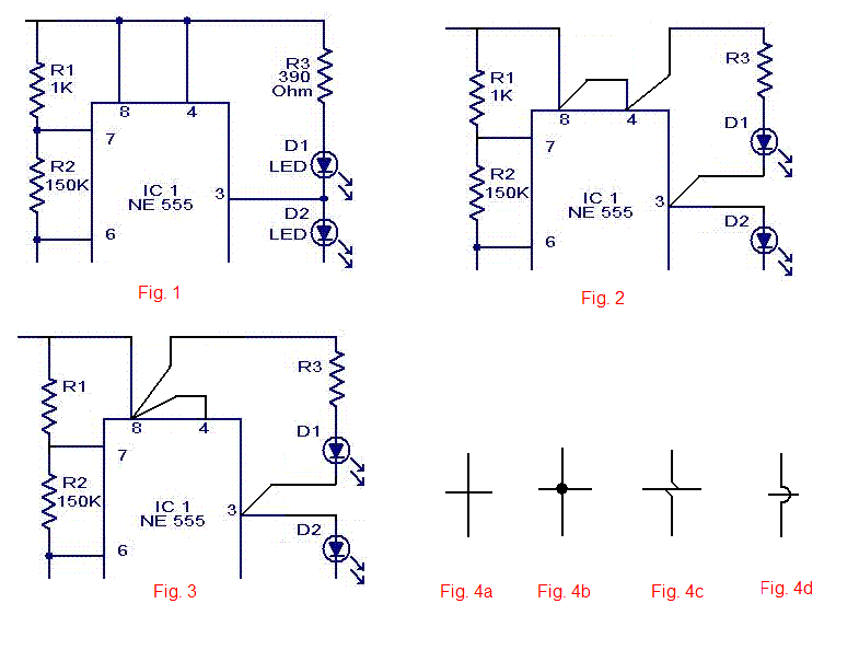
Figs. 1, 2 and 3 below are electrically identical, but neither of them should be taken as an indication of the actual physical placement or wiring.


Dots placed at electrical junctions/connections generally serve no useful purpose in my opinion.
However, look at Fig. 4a. What the hell is that supposed to mean? It's ambiguous.

Fig. 4b clearly shows a connection between all four branches, but Fig. 4c is preferred.

Fig. 4d shows wires crossing.


readingcircuits.gif
 

Instead of saying R3 is connected to Pin4, you should think of it this way:
-R3 is connected to +9v supply through switch S1
-Pin4 is also connected to +9v supply through switch S1
-Pin8 is also connected to +9v supply through switch S1
-R1 is also connected to +9v supply through switch S1
 

It seems none of the posts is helpful to rotary. He may split his question into pieces and resolve issues one by one
 

Thanks for all your replies, I have now made the circuit and got it working.
 
Status
Not open for further replies.

Similar threads

Part and Inventory Search

Welcome to EDABoard.com

Sponsor

Back
Top