Continue to Site

Welcome to EDAboard.com

Welcome to our site! EDAboard.com is an international Electronics Discussion Forum focused on EDA software, circuits, schematics, books, theory, papers, asic, pld, 8051, DSP, Network, RF, Analog Design, PCB, Service Manuals... and a whole lot more! To participate you need to register. Registration is free. Click here to register now.

[SOLVED] Prevent MCU from being affected by motor current: is capacitor enough?

Status
Not open for further replies.

bobsun

Full Member level 2
Joined
Mar 5, 2011
Messages
120
Helped
0
Reputation
0
Reaction score
0
Trophy points
1,296
Activity points
2,239
Hello,

I would like to ask a question on motor circuit isolation.

If I use MCU to control H-Bridge, which in turn drives a small stepper motor, would the rapid rise and fall of motor current disrupt MCU’s electric environment?

Some parameters are here:
1. MCU core voltage: 1.2V
2. Motor speed: <60 steps/second
3. Motor current: <1A
4. H-Bridge supply voltage: 5V

This is in fact a very small motor, as well as being both low voltage and low speed. Although I am a newbie with motor circuit, it seems like that the disruption would not be very significant.

Would a capacitor be enough here? If I connect a capacitor to 5V H-bridge supply, another end to ground, then it will get charged when the motor is off, and would discharge to power the motor when H-Bridge is turned on. And since the motor speed, and consequently, H-Bridge on and off frequency is also as slow as 60Hz, could this solution work?

Or, if it would not work, do I need to use optocoupler or digital isolation?

Could any experienced designers here off some suggestions?


Bob
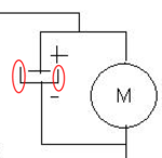
 

There are some things you could do about MCU protection from spikes generated by the motor. The most important maybe would be the return path of the motor current. If you just see a schematic you will see a ground symbol connected to one of the motor's edges (through the H-bridge switch of course), and a ground symbol connected to the MCU. But the path must not be the same. You have a positive supply voltage. After that there must be a big capacitor. From the capacitor negative pin, a ground should be driven to the H-bridge and nowhere else. All other grounds should not be confused with this one. Do that with the motor's positive supply also. So you will have a closed loop 5V - HBridge - GND and no other components will take signals from that loop (except from the measurement circuits of course). The loop will be starting from the capacitor's '+' and will end at the capacitor's '-'. Then the capacitor would make sence. Optical isolation would obviously be safer, but more expensive also.
 
  • Like
Reactions: bobsun

    bobsun

    Points: 2
    Helpful Answer Positive Rating
alexxx,

Could you post a schematics like you just described? I found it a bit difficult to fully imagine it out, and am not sure if I got it correct.

Bob
 

I searched but didn't find a layout example on this. I did something quick using painting (please forgive me about the image, I was never famous on my drawing abilities).:smile:

View attachment layout example dc motor.rar

This drawing is try to tell you that if you are to supply a logic device, then its ground should be taken from the capacitor's pin and not from the motor path (by the way I was too lazy for the H-bridge, I think you get the idea just with the motor).:smile:
 
  • Like
Reactions: bobsun

    bobsun

    Points: 2
    Helpful Answer Positive Rating
Alex,

power_alex_capacitor.png

One quick question: The capacitor should be two parallel lines, but in the diagram one line has additional two bends. Do you mean just an ordinary capacitor?

BTW, I guess it is perhaps some drawing software artifacts.


Bob
 

bobsun said:
I guess it is perhaps some drawing software artifacts.

My first boss was demanding to design the electrolytic capacitors in that way and I kinda stuck on it! So it is not a software artifact but my mind's artifact!:-D
 
  • Like
Reactions: bobsun

    bobsun

    Points: 2
    Helpful Answer Positive Rating
Alex,

I still have some doubt on it, and I actually think the proper way was to used two Voltages sources/batteries, and connecting their GND together. In your example how many voltage sources did you mean? I only see the electrolytic capacitor, but not any voltage source explicitly. What is your implicitly assumption?

I have found one example. I noticed that there are two voltages in the schematics: (1) VCC5.0, for L298N H-Bridge Driver internal logic (2) VCC36, for the real motor.

The two network only shares GND together. It is like too loops touching at one point, but current never runs from one to another. It is always like being "tangent".


Bob
 

Attachments

  • L298N Schematics.pdf
    1 MB · Views: 97

bobsun said:
I still have some doubt on it, and I actually think the proper way was to used two Voltages sources/batteries, and connecting their GND together.

If you just see a schematic you will see a ground symbol connected to one of the motor's edges (through the H-bridge switch of course), and a ground symbol connected to the MCU. But the path must not be the same.

Of course they are grounded together or else it could not work. But motor's ground and logic ground must be merged in a single place only. And that place is the capacitor's '-'. Like that pretty drawing I posted earlier.:smile: Logic ground and motor ground share just one common point at the capacitor.
 
Last edited:
  • Like
Reactions: bobsun

    bobsun

    Points: 2
    Helpful Answer Positive Rating
while the suggestion of h-bridge power cap is good to solve the problem ,
can you test the old setup with a good supply for the mcu?

do the mcus power supply adequately noise free/ or is there any suppression in mcu power pins ?
 
  • Like
Reactions: bobsun

    bobsun

    Points: 2
    Helpful Answer Positive Rating
@bob: I opened an old design with DC motor control using H-bridge. I posted a snapshot of the big capacitor just to see what I mean.

View attachment mergeExample.rar

There are four tracks, all ground and marked with arrows and numbers. This numbers represent:

1. Ground track coming from the power source (rectifier bridge and battery).
2. Ground track returning from the motor.
3. Ground tracks (two of them as you can see), going to the logic circuitry. They share the same number because they both go to logic circuits, and so you can think of them as the same ground just like I do.

As you can see, those grounds are connected to each other. The track from the rectifier goes to the capacitor and nowhere else. All digital circuits take ground from this capacitor. And finally the motor return path comes to this capacitor as well. Those three grounds are not met with each other at any other point of the board, except from this big electrolytic capacitor. Of course further precautions can be taken like bypass capacitors next to ICs, but this is the cornerstone of all other protections: don't mess power ground with digital ground in your layout design!


I hope it is more clear for you now.
 
Last edited:
  • Like
Reactions: bobsun

    bobsun

    Points: 2
    Helpful Answer Positive Rating
Alex and srizbf,

Sorry for replying late. I looked at Alex's example and believe the problem is solved.

Bob
 

Status
Not open for further replies.

Similar threads

Part and Inventory Search

Welcome to EDABoard.com

Sponsor

Back
Top