Vermes
Advanced Member level 4

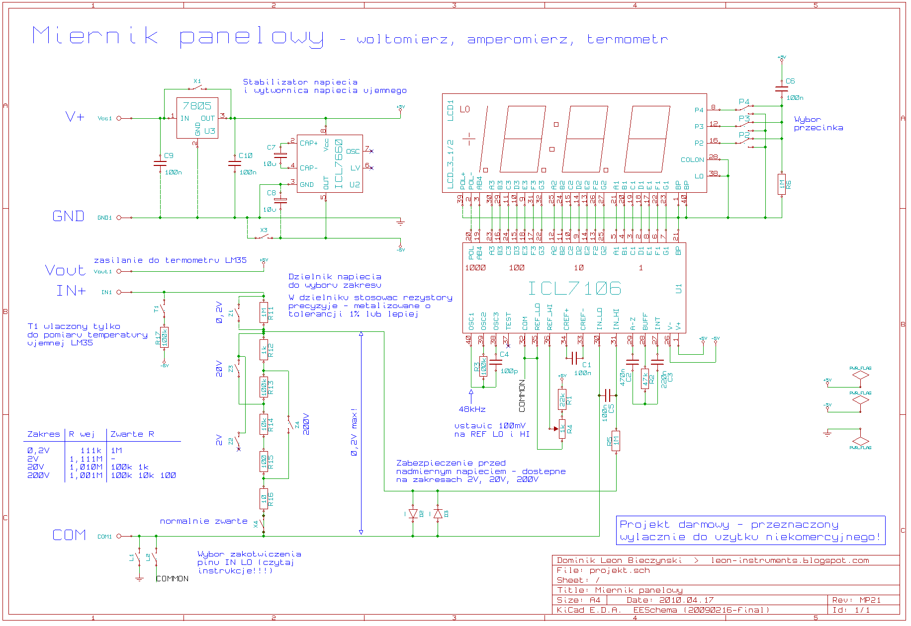
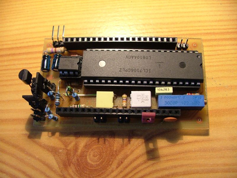
Chips ICL7106 (for LCD display) and ICL7107 (for LED display) are phenomenon in electronics. Although they were designed 30 years ago, they are still in use. Despite many attempts, such as integrating a converter, adding the HOLD function, chips ICL7106 and ICL7107 are still the best in measuring devices.
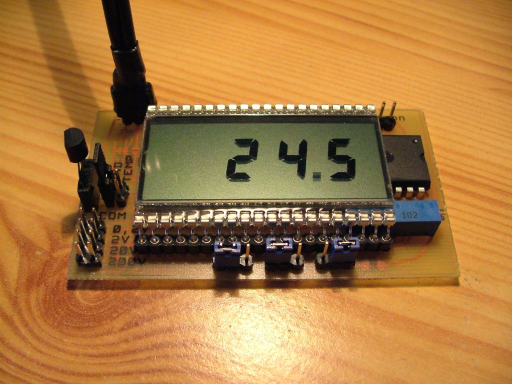
Presented here panel meter is to measure all sizes, which can be expressed through a constant voltage – for example, current and temperature.
The device has the following functions:
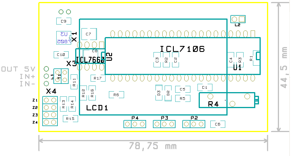
- integrated voltage divider, allowing to measure voltage ranges up to 0,2V, 2V, 20V, 200V. The divider switched by jumpers in the plate, and if necessary, it can be cut off from the system
- protection against excessive voltage at the measurement inputs
- 'supply from anything' – a power plug, integrated stabilizer
- built-in negative voltage generator – you do not have to bother with the issue of power supply
- IN LO input can be connected to the ground, COMMON or not at all – with a jumper on the plate
- adapted to work with LM35 thermometer – just stick it in the appropriate socket on the plate
- selection of a comma with a jumper on the plate
- after minor alterations, it is possible to measure the ratio of two quantities

Instruction
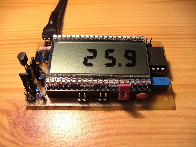
The meter should be powered by voltage not less than 7V, if you want to use 7805 stabilizer mounted on the plate. When the stabilized voltage is in the system, X1 jumper can be soldered on the plate and the stabilizer can be bypassed this way. Then the supply voltage can be 3,3V (recommended no less than 5V).
After first starting, the meter has to be calibrated. To do this, connect a voltmeter to pins 35 (REF LO) and 36 (REF HI), and then set the R4 potentiometer so that the voltmeter shows exactly 100mV.
Ranges of input voltages can be adjusted by jumper on the left side of the plate. Overflow the range should not cause damage to the meter, because diodes protecting the inputs were used. NOTE – the protection does not apply to the range 0,2V!! When the jumper is not inserted in any position, then the range is set to 2V.
When the meter and the measured system are powered by different sources, set the jumper COMMON. When the meter and the system are powered by the same source, then this jumper must be removed.
Panel meter allows direct connection of thermometer LM35 and powering it from the same source as the meter. You just need to put jumpers on GND and TEMP.
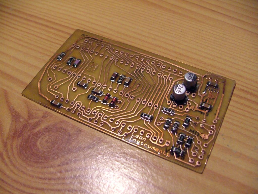
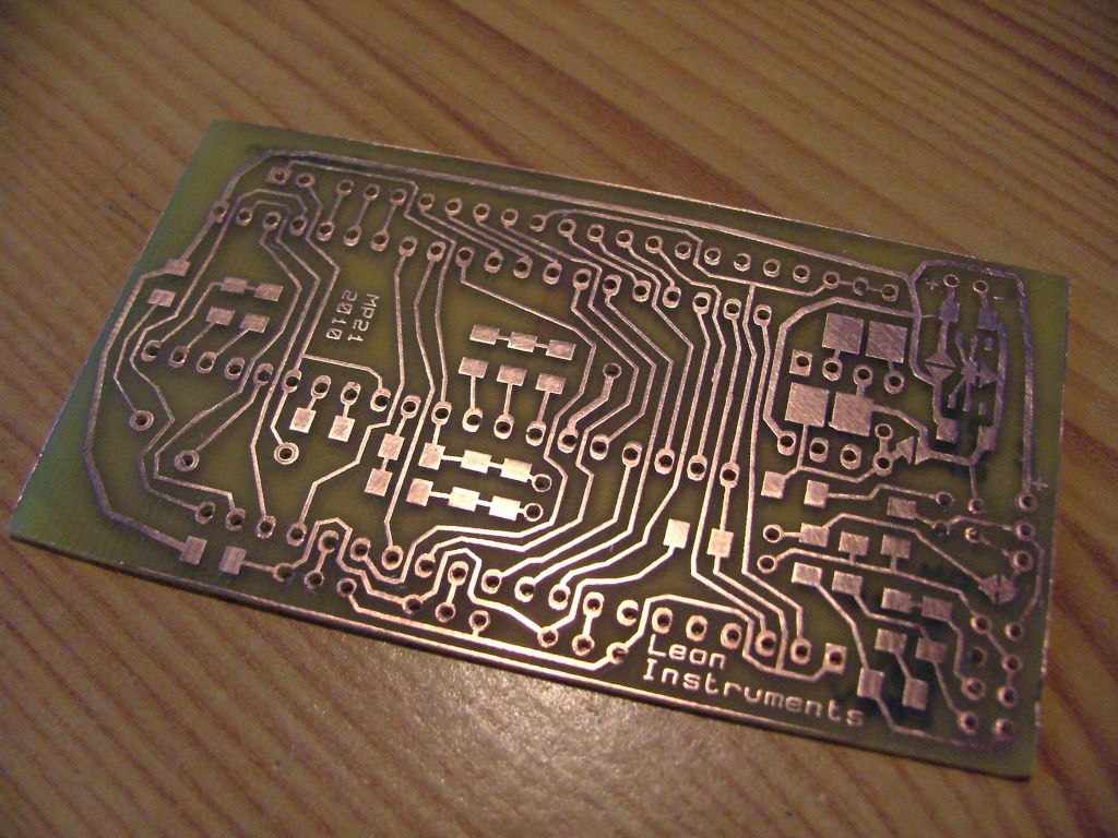
SMD version
It was assembled by the heating plate method (it is really simple method using iron):
- soldering boxes have to be tinned
- additionally, the boxes should be painted with rosin, so the components would stick and tin better stick to them
- set the elements
- turn on heating
- after a while, all items should be neatly soldered
- the hole components should be hand soldered
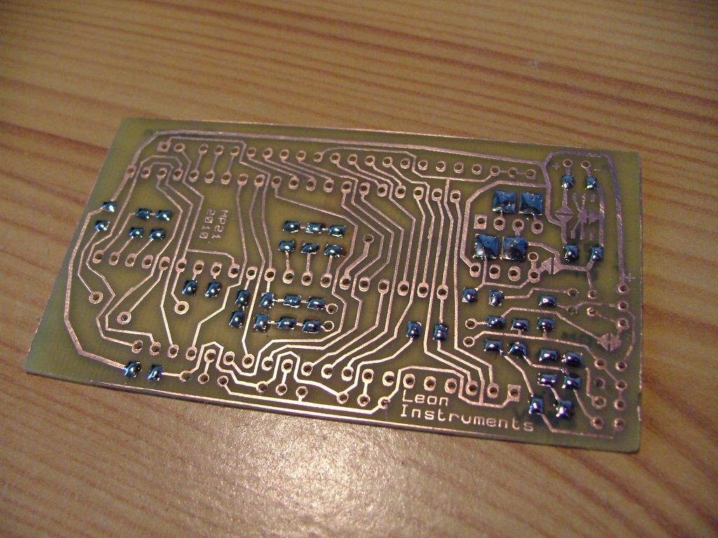
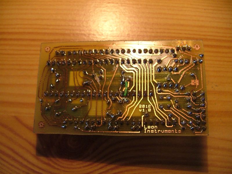
THT version
It was made earlier than SMD. Design was a really big trouble. The design had to be improved many times to ensure that the elements do not fall on each other.

Link to original thread (attachment) – Miernik panelowy ICL7106: woltomierz, amperomierz, termometr