Continue to Site

Welcome to EDAboard.com

Welcome to our site! EDAboard.com is an international Electronics Discussion Forum focused on EDA software, circuits, schematics, books, theory, papers, asic, pld, 8051, DSP, Network, RF, Analog Design, PCB, Service Manuals... and a whole lot more! To participate you need to register. Registration is free. Click here to register now.

step response of an RC circuit

Status
Not open for further replies.

PG1995

Full Member level 5
Joined
Apr 18, 2011
Messages
248
Helped
1
Reputation
2
Reaction score
1
Trophy points
1,298
Activity points
3,758
Hi

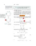
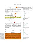
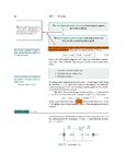
Please have a look on the attachments. The attached pages are: 258, 259, 260. Please help me with the queries. I need to understand this derivation soon. Thank you for your help.

Regards
PG
 

Attachments

  • Fundamental of Electric Circuits - Alexander Sadiku_0262.jpg
    Fundamental of Electric Circuits - Alexander Sadiku_0262.jpg
    297.7 KB · Views: 81
  • Fundamental of Electric Circuits - Alexander Sadiku_0263.jpg
    Fundamental of Electric Circuits - Alexander Sadiku_0263.jpg
    430.2 KB · Views: 88
  • Fundamental of Electric Circuits - Alexander Sadiku_0264.jpg
    Fundamental of Electric Circuits - Alexander Sadiku_0264.jpg
    334.2 KB · Views: 83

Looks as though yet another textbook writer has generated verbiage about concepts that are easier for us to grasp by building a circuit and watching a meter, than by our having to memorize idiosyncratic terminology.

It is true that a capacitor shows behavior A in one instance, and behavior B in the other instance. After seeing these demonstrated a few times you'll think of these behaviors with a more intuitive part of your brain.

Nevertheless for the time being you may as well let the author have his day. The math has a beauty to it, and the concepts he uses will turn up as applied to other topics, most likely in vital connections.

So take in whatever concepts jibe with what you learn as you work with real components.

He says something about transient response. As for me the only real criterion I know of is that capacitor response is transient when enough time goes by that the cap attains whatever voltage is applied to it. Five time constants is the convention. The curve has the well-known look to it: drops quickly at first, then tapers to horizontal.

On the other hand if voltage changes before 5 time constants go by, the capacitor has a new situation to adapt to, and it manifests the other type of response. (Whatever the author calls it. Didn't he use the term 'forced response' somewhere? I cannot fathom what that might mean as applied to a capacitor.)

There are some important distinctions the author brings out. There are cases where you do want a capacitor to fully charge (or discharge). And other cases where you do not.

How do we talk in everyday life? We might say 'it's discharging too fast, use more microfarads', or 'substitute a larger value resistor', etc. A textbook on the other hand can't talk like we do in everyday life.

A textbook needs to be hard to read, or else the purchaser will get the idea it's only for beginners, and won't buy it.

In any case you'll think of your own terminology for these concepts as time goes by. Or maybe you won't think in words at all. It will become second nature to you.
 
Last edited:
  • Like
Reactions: PG1995

    PG1995

    Points: 2
    Helpful Answer Positive Rating
Certainly the book uses non conventional terminology.
When the switch of 7.40a is switched on what all happens in the initial stages (may be 3-5 time constants) is called as transient response and what happens later is called as forced.
Regarding Q1 related to fig 7.40b what I understand is that the switching is replaced by assigning ma mathematical feature to the input voltage source itself. This simplifies appearance of the circuit but included additional feature to the representation of the voltage source (including the property of switch).
This is accomplished using the function u(t). It seems a unit step function whose value is zero for t < 0 and is 1 for t > 0, implying that the voltage is applied to the circuit at t = 0 (as shown in Fig 7.40a).
Doing this assignment (use of u(t)) provides many advantages in circuit analysis like solving the differential equation using Laplace transform.
 

Status
Not open for further replies.

Part and Inventory Search

Welcome to EDABoard.com

Sponsor

Back
Top