Chris1990
Junior Member level 1
Hi anyone reading this.
my problem involves a hall sensor, analogue output, operating at 3.3V, i wish to amplify the signal from the hall sensor, only one half though..?
the hall sensors provides a constant output of half vcc (1.65Vish in this case) [This is the hall sensor: https://sensing.honeywell.com/index.cfm/ci_id/141050/la_id/1/document/1/re_id/0]
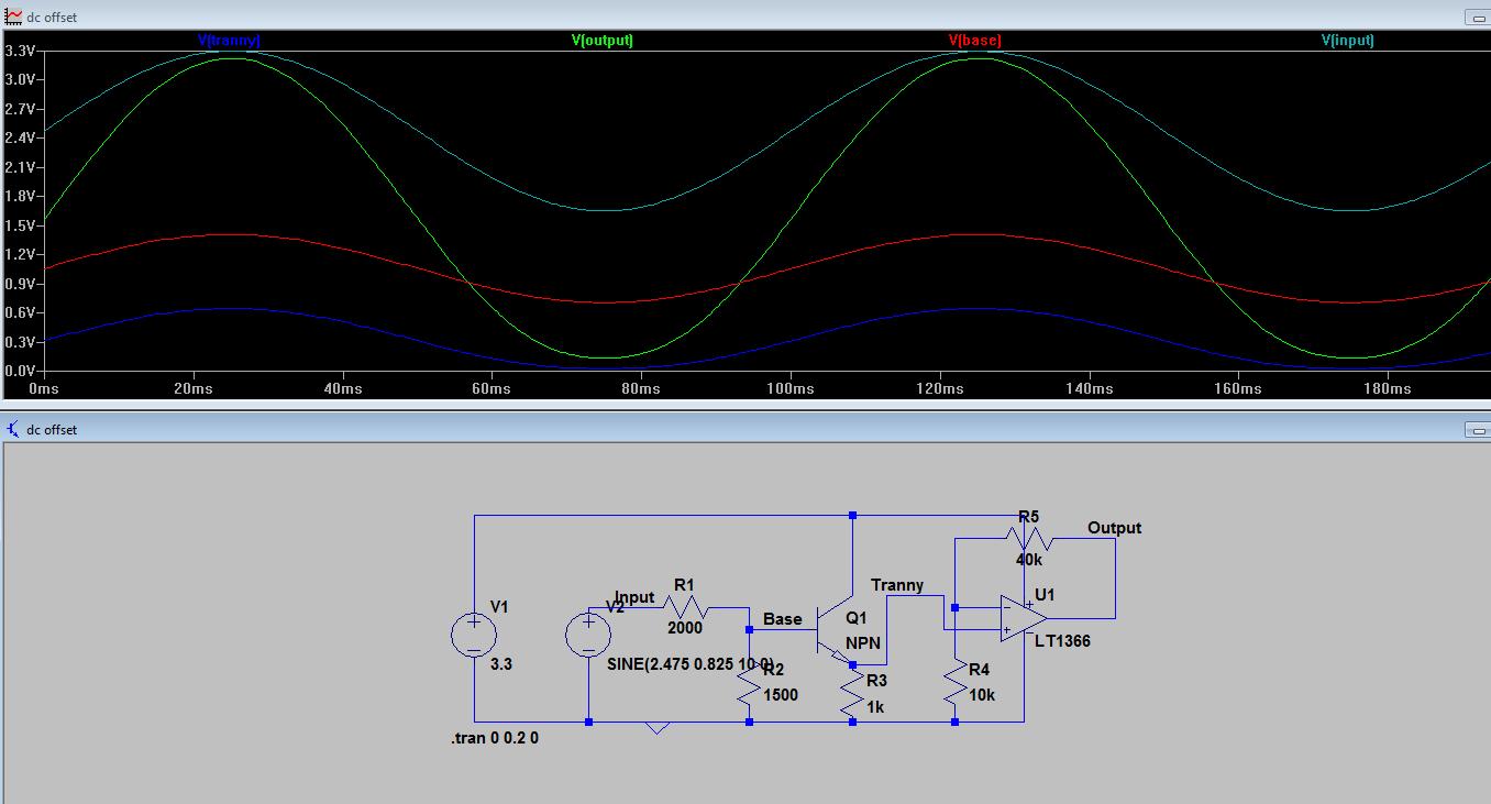
seeing as i will only be using one side of the magnet, i.e. one pole, and therefore not using the signal lower than 1.65, i wish to find someway of amplifying the signal, making 1.65V into 0V, and making the maximum voltage out around 3.3V.
I hope this makes sense and would be very grateful for any help, i have looked into differential op-amps but simulating this it doesnt output how i want.
Chris
my problem involves a hall sensor, analogue output, operating at 3.3V, i wish to amplify the signal from the hall sensor, only one half though..?
the hall sensors provides a constant output of half vcc (1.65Vish in this case) [This is the hall sensor: https://sensing.honeywell.com/index.cfm/ci_id/141050/la_id/1/document/1/re_id/0]
seeing as i will only be using one side of the magnet, i.e. one pole, and therefore not using the signal lower than 1.65, i wish to find someway of amplifying the signal, making 1.65V into 0V, and making the maximum voltage out around 3.3V.
I hope this makes sense and would be very grateful for any help, i have looked into differential op-amps but simulating this it doesnt output how i want.
Chris