Continue to Site

Welcome to EDAboard.com

Welcome to our site! EDAboard.com is an international Electronics Discussion Forum focused on EDA software, circuits, schematics, books, theory, papers, asic, pld, 8051, DSP, Network, RF, Analog Design, PCB, Service Manuals... and a whole lot more! To participate you need to register. Registration is free. Click here to register now.

[SOLVED] Mathematical Formula for given circuit ?

Status
Not open for further replies.

sameerdhiman

Member level 5
Joined
Dec 1, 2009
Messages
82
Helped
1
Reputation
2
Reaction score
1
Trophy points
1,288
Location
India
Activity points
1,966
Hi,

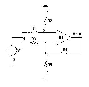
Can somebody give me the mathematical formula for the following circuit.

Where R1≠R2≠R3≠R4, R5 is variable. Calculate Vout for any V1 value.

49_1318009408.jpg
 

To make it a simple network calculation problem you have to assume an ideal OP with infinite input resistance and gain. Then Vout will be always controlled so that the input OP difference voltage becomes zero. This gives you the oportunity to apply a basic network calculation method of your choice.
 

Hi FvM,

I simulated the circuit under LTSpice with the following values.
Ideal OpAmp:
.subckt ideal-opamp 1 2 3
G1 0 3 1 2 100Meg
.ends ideal-opamp

R1=10K, R2=270, R3=1K5, R4=560 and R5=27.5, V1=1Vpk-1KHz, Vout=0.198133

Calculation Used:
Non-Inverting Vninv = V1×[R2/(R2+R1)]×[1+(R4/R5)], So Vninv = 0.561649
Inverting Vinv = V1×-(R4/R3), So Vinv = -0.373333
Therefore Vout = Vninv + Vinv, Vout = 0.188316

What I am missing ?
 

Vninv = V1×[R2/(R2+R1)]×[1+(R4/R5)]
You are using a superposition method to calculate the output voltage. In this case R3 has to be connected parallel to R5 for the noninverting case.

Your "ideal OpAmp" is an OTA, by the way. You should use a voltage controlled voltage source to model an OP. But both can work in this circuit.
 
Thank you so much FvM :smile:

Vninv = V1×[R2/(R2+R1)]×[1+{R4/(R5||R3}]

---------- Post added at 16:16 ---------- Previous post was at 15:51 ----------

May I know why we put R3 parallel to R5 ?
 

Superposition method involves that you're supplying input voltage to +ve and -ve branche seperately. The other input is connected to zero input voltage. Zero input voltage means paralleling both resistors.
 
Status
Not open for further replies.

Similar threads

Part and Inventory Search

Welcome to EDABoard.com

Sponsor

Back
Top