Continue to Site

Welcome to EDAboard.com

Welcome to our site! EDAboard.com is an international Electronics Discussion Forum focused on EDA software, circuits, schematics, books, theory, papers, asic, pld, 8051, DSP, Network, RF, Analog Design, PCB, Service Manuals... and a whole lot more! To participate you need to register. Registration is free. Click here to register now.

Starting with PIC 18F2550 and LCD display

Status
Not open for further replies.

Felipebrz

Newbie level 4
Joined
Oct 8, 2007
Messages
6
Helped
0
Reputation
0
Reaction score
0
Trophy points
1,281
Activity points
1,348
Hi,
I'm just starting on the 18F family (using the 18F2550) and with the C18 compiler.
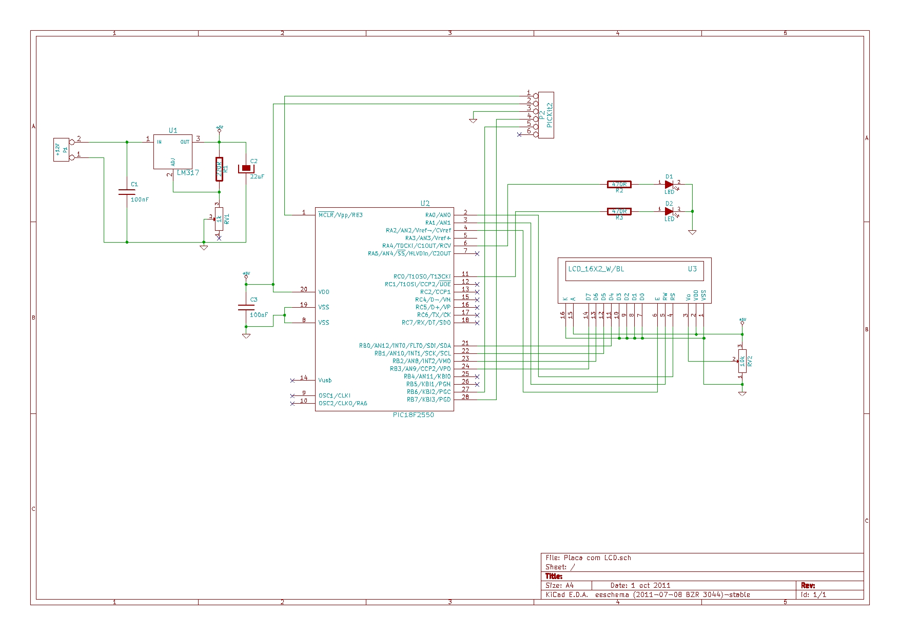
I created a circuit with two LEDs and the LCD. First I did a simple blinking leds example with it, which worked perfectly. I'm using the internal oscilator, configured to 8MHz.
The LCD only has written 1602F REV:I behind it, so I assume thats the LCD's controller. I've counted the dot matrix for each character and it looks like it is a 5x8 (even though it doesnt mention this kind in the xlcd library)
I am using MPLAB v8.73 and C18 v3.40. And using a PICkit2 to program my PIC.

Seeing examples around the net, I have connected the LCD pins D4-D7 to RB0-RB3, while RS=RA0, RW=RA1 and E=RA2.

The main .c file is:
Code:
// Arquivos de cabeçalho
#include <p18f2550.h>			// Processador = 18F2550
#include <delays.h>				// Funções de delay do compilador C18:
#include <string.h>
#include "xlcd.h"				// Funções do display LCD 2x16
// 1 TCY = 4/FOSC ==> @ 8 MHz ==> 1 TCY = 0,5 us
//		Delay1TCY()		= 0,5 us
//		Delay10TCYx()	= 5 us
//		Delay100TCYx()	= 50 us
//		Delay1KTCYx()	= 500 us	= 0,5 ms
//		Delay10KTCYx()	= 5000 us	= 5 ms

// Configurações do processador
#pragma config PLLDIV = 1
#pragma config CPUDIV = OSC1_PLL2
#pragma config FOSC = INTOSCIO_EC		// Oscilador interno
#pragma config FCMEN = OFF
#pragma config IESO = OFF				// Troca de oscilador desabilitada
#pragma config PWRT = OFF				// Habilita o Power-up Timer (PWRT)
#pragma config BOR = OFF				// Brown-out Reset (BOR) habilitado somente no hardware
#pragma config VREGEN = ON				// Regulador de tensão da USB habilitado
#pragma config WDT = OFF				// Desabilita o Watchdog Timer (WDT)
#pragma config MCLRE = OFF				// MCLR desabilitado; RE3 = Input
#pragma config PBADEN = OFF				// RB0,1,2,3 e 4 configurado como I/O digital.
#pragma config LVP = OFF				// Desabilita o Low Voltage Program
#pragma config XINST = OFF				// Conjunto de instruções extendido desabilitado
#pragma config DEBUG = OFF				// Debugger desabilitado
#pragma config CP0 = OFF				// Proteção do bloco 0 desabilitada
#pragma config CP1 = OFF				// Proteção do bloco 1 desabilitada
#pragma config CP2 = OFF				// Proteção do bloco 2 desabilitada
#pragma config CP3 = OFF				// Proteção do bloco 3 desabilitada
#pragma config CPB = OFF				// Proteção do bloco de boot desabilitada
#pragma config CPD = OFF				// Proteção do bloco da EEPROM desabilitada
#pragma config WRT0 = OFF				// Proteção de escrita do bloco 0 desabilitada
#pragma config WRT1 = OFF				// Proteção de escrita do bloco 1 desabilitada
#pragma config WRT2 = OFF				// Proteção de escrita do bloco 2 desabilitada
#pragma config WRT3 = OFF				// Proteção de escrita do bloco 3 desabilitada
#pragma config WRTB = OFF				// Proteção de escrita do bloco de boot desabilitada
#pragma config WRTC = OFF				// Proteção de escrita do bloco de config desabilitada
#pragma config WRTD = OFF				// Proteção de escrita do bloco da EEPROM desabilitada

// Definições de variáveis de IO:
#define VERMr	PORTCbits.RC0			// LED vermelho grande (pino 11): leitura
#define VERMw	LATCbits.LATC0			// LED vermelho grande (pino 11): escrita
#define VERDr	PORTAbits.RA4			// LED verde grande (pino 6): leitura
#define VERDw	LATAbits.LATA4			// LED verde grande (pino 6): escrita

// Rotinas auxiliares
void DelayFor18TCY(void)
{
Nop();
Nop();
Nop();
Nop();
Nop();
Nop();
Nop();
Nop();
Nop();
Nop();
Nop();
Nop();
}

void DelayPORXLCD(void)
{
Delay1KTCYx(30);	// Delay of 15ms
					// Cycles = (TimeDelay * Fosc) / 4
					// Cycles = (15ms * 8MHz) / 4
					// Cycles = 30,000
return;
}

void DelayXLCD(void)
{
Delay1KTCYx(10);	// Delay of 5ms
					// Cycles = (TimeDelay * Fosc) / 4
					// Cycles = (5ms * 8MHz) / 4
					// Cycles = 10,000
return;
}

unsigned char lcd[17];

// Início do programa
void main(void)
{
Delay10KTCYx(190);
// Definição das variáveis locais

// Configurações de módulos
OSCCONbits.IRCF2=1;	// Configuração para clock de 8 MHz
OSCCONbits.IRCF1=1;
OSCCONbits.IRCF0=1;
OSCCONbits.SCS1=1;	// Oscilador interno para sistema
ADCON0=0b00000000;	// Módulo AD desligado (pag.265)
ADCON1=0b00001111; 	// Todas as portas são digitais (pag.266)
CMCON=0b00000111;	// Desliga os comparadores (pag. 277 e 278)

// Configuração de direção das portas
TRISA=0b00000000;
TRISB=0b00000000;
TRISC=0b00000000;

LATA=0b00000000; //Coloca o PORTA em 0V.
LATB=0b00000000; //Coloca o PORTA em 0V.
LATC=0b00000000; //Coloca o PORTA em 0V.

// Configurando LCD
OpenXLCD(FOUR_BIT & LINES_5X7);
while(BusyXLCD());
WriteCmdXLCD(DON & BLINK_OFF & CURSOR_OFF);
while(BusyXLCD());
WriteCmdXLCD(0x01);//clear display
memset(lcd,'\0',17);
strcpypgm2ram(lcd,"hello world");
putsXLCD(lcd); 
while(1)
{
;
}
}

Below are the modified parts of the xlcd.h file:
Code:
#ifndef __XLCD_H
#define __XLCD_H
#include "p18f2550.h"
/* PIC18 XLCD peripheral routines.
 *
 *   Notes:
 *      - These libraries routines are written to support the
 *        Hitachi HD44780 LCD controller.
 *      - The user must define the following items:
 *          - The LCD interface type (4- or 8-bits)
 *          - If 4-bit mode
 *              - whether using the upper or lower nibble
 *          - The data port
 *              - The tris register for data port
 *              - The control signal ports and pins
 *              - The control signal port tris and pins
 *          - The user must provide three delay routines:
 *              - DelayFor18TCY() provides a 18 Tcy delay
 *              - DelayPORXLCD() provides at least 15ms delay
 *              - DelayXLCD() provides at least 5ms delay
 */

/* Interface type 8-bit or 4-bit
 * For 8-bit operation uncomment the #define BIT8
 */
/* #define BIT8 */

/* When in 4-bit interface define if the data is in the upper
 * or lower nibble.  For lower nibble, comment the #define UPPER
 */
/* #define UPPER */

/* DATA_PORT defines the port to which the LCD data lines are connected */
 #define DATA_PORT      		PORTB
 #define TRIS_DATA_PORT 		TRISB

/* CTRL_PORT defines the port where the control lines are connected.
 * These are just samples, change to match your application.
 */
 #define RW_PIN   LATAbits.LATA1   		/* PORT for RW */
 #define TRIS_RW  TRISAbits.TRISA1    	/* TRIS for RW */

 #define RS_PIN   LATAbits.LATA0   		/* PORT for RS */
 #define TRIS_RS  TRISAbits.TRISA0    	/* TRIS for RS */

 #define E_PIN    LATAbits.LATA2  		/* PORT for D  */
 #define TRIS_E   TRISAbits.TRISA2    	/* TRIS for E  */

on the project tree I have:
Source files:
- LCD.c
Header files:
- delays.h (in the same folder as LCD.c)
- p18f2550.h
- string.h (in the same folder as LCD.c)
- xlcd.h (in the same folder as LCD.c)
Linker script:
- 18f2550_g.lkr

And after all that, my LCD shows nothing!
I tried adjusting the brightness (using a 10k pot) but thats not the problem.
Can anyone help me with this? Any other information that may help, just say so.

Thanks!
 

Can you post or upload a schematic of your circuit? Have you tied the unused D0-D3 lines of the LCD to ground?

Usually these types of issues with the LCD are due to improper initialization. You might try add a delay of 200ms at the top of main() before any other routines are executed. Is the LCD library that you're using the demo library in C18 or PICC18 compilers?

BigDog

I'll get an schematic and post it here, but i can tell you that the D0-D3 are not grounded. So they should?
 

I'll get an schematic and post it here, but i can tell you that the D0-D3 are not grounded. So they should?

Yes, tie them to ground. Here is a typical HD44780 compatible 4-bit interface:

LCD4Bit.jpg

Leave the R/W line as you already have it connected.


BigDog
 

Yes, tie them to ground. Here is a typical HD44780 compatible 4-bit interface:
Leave the R/W line as you already have it connected.


BigDog

And what about it being this 1602F model? Is it compatible to this HD44780?
Also, there's the thing I said about each character being 5x8 and it only has, in the xlcd.h, the option of 5x7 or 5x10. Does this matter at all?
I can't really see the controller as there are two black blobs on the circuit, which i suppose are the controler and driver.


Felipe
 

And what about it being this 1602F model? Is it compatible to this HD44780?

Yes, I believe that display has either a KS0066 or SPLC780A, both of which are compatible with the HD44780.

Also, there's the thing I said about each character being 5x8 and it only has, in the xlcd.h, the option of 5x7 or 5x10. Does this matter at all?

The 5x7 characters are actually 5x8, usually the bottom row (8th) is left blank for the cursor. The HD44780 also support the 5x10 characters as well.

I can't really see the controller as there are two black blobs on the circuit, which i suppose are the controler and driver.

Yes, that what those black blobs are the LCD controllers/drivers, common practice for inexpensive LCDs.

BigDog
 

Can you post or upload a schematic of your circuit? Have you tied the unused D0-D3 lines of the LCD to ground?

Usually these types of issues with the LCD are due to improper initialization. You might try add a delay of 200ms at the top of main() before any other routines are executed. Is the LCD library that you're using the demo library in C18 or PICC18 compilers?

BigDog

Hi BigDog,

I uploaded a schematic of the circuiti, I already tied to pins to the ground which did not work with the previous code (the one posted above). I'll add the 200 ms and try again and let you know.


I already tied to pins to the ground which did not work with the previous code (the one posted above).

At least it will prevent any floating leads from creating additional issues.

I'll add the 200 ms and try again and let you know.

The LCD basically has its own limited MCU, which must boot into a known state after the applied voltage reaches a specific level. The powerup process usually ranges from 100ms to 200ms, a longer than needed delay before performing the initialization procedure has no ill effect.

BigDog
 

At least it will prevent any floating leads from creating additional issues.


The LCD basically has its own limited MCU, which must boot into a known state after the applied voltage reaches a specific level. The powerup process usually ranges from 100ms to 200ms, a longer than needed delay before performing the initialization procedure has no ill effect.

BigDog

Hi there, sorry for the delay in replying. I got some time to test the suggestions out and created the following code:

Code:
// Arquivos de cabeçalho
#include <p18f2550.h>			// Processador = 18F2550
#include <delays.h>				// Funções de delay do compilador C18:
#include <string.h>
#include "xlcd.h"				// Funções do display LCD 2x16
// 1 TCY = 4/FOSC ==> @ 8 MHz ==> 1 TCY = 0,5 us
//		Delay1TCY()		= 0,5 us
//		Delay10TCYx()	= 5 us
//		Delay100TCYx()	= 50 us
//		Delay1KTCYx()	= 500 us	= 0,5 ms
//		Delay10KTCYx()	= 5000 us	= 5 ms

// Configurações do processador
#pragma config PLLDIV = 1
#pragma config CPUDIV = OSC1_PLL2
#pragma config FOSC = INTOSCIO_EC		// Oscilador interno
#pragma config FCMEN = OFF
#pragma config IESO = OFF				// Troca de oscilador desabilitada
#pragma config PWRT = OFF				// Habilita o Power-up Timer (PWRT)
#pragma config BOR = OFF				// Brown-out Reset (BOR) habilitado somente no hardware
#pragma config VREGEN = ON				// Regulador de tensão da USB habilitado
#pragma config WDT = OFF				// Desabilita o Watchdog Timer (WDT)
#pragma config MCLRE = OFF				// MCLR desabilitado; RE3 = Input
#pragma config PBADEN = OFF				// RB0,1,2,3 e 4 configurado como I/O digital.
#pragma config LVP = OFF				// Desabilita o Low Voltage Program
#pragma config XINST = OFF				// Conjunto de instruções extendido desabilitado
#pragma config DEBUG = OFF				// Debugger desabilitado
#pragma config CP0 = OFF				// Proteção do bloco 0 desabilitada
#pragma config CP1 = OFF				// Proteção do bloco 1 desabilitada
#pragma config CP2 = OFF				// Proteção do bloco 2 desabilitada
#pragma config CP3 = OFF				// Proteção do bloco 3 desabilitada
#pragma config CPB = OFF				// Proteção do bloco de boot desabilitada
#pragma config CPD = OFF				// Proteção do bloco da EEPROM desabilitada
#pragma config WRT0 = OFF				// Proteção de escrita do bloco 0 desabilitada
#pragma config WRT1 = OFF				// Proteção de escrita do bloco 1 desabilitada
#pragma config WRT2 = OFF				// Proteção de escrita do bloco 2 desabilitada
#pragma config WRT3 = OFF				// Proteção de escrita do bloco 3 desabilitada
#pragma config WRTB = OFF				// Proteção de escrita do bloco de boot desabilitada
#pragma config WRTC = OFF				// Proteção de escrita do bloco de config desabilitada
#pragma config WRTD = OFF				// Proteção de escrita do bloco da EEPROM desabilitada

// Definições de variáveis de IO:
#define VERMr	PORTCbits.RC0			// LED vermelho grande (pino 11): leitura
#define VERMw	LATCbits.LATC0			// LED vermelho grande (pino 11): escrita
#define VERDr	PORTAbits.RA4			// LED verde grande (pino 6): leitura
#define VERDw	LATAbits.LATA4			// LED verde grande (pino 6): escrita

// Rotinas auxiliares
void DelayFor18TCY(void)
{
Nop();
Nop();
Nop();
Nop();
Nop();
Nop();
Nop();
Nop();
Nop();
Nop();
Nop();
Nop();
}

void DelayPORXLCD(void)
{
Delay1KTCYx(30);	// Delay of 15ms
					// Cycles = (TimeDelay * Fosc) / 4
					// Cycles = (15ms * 8MHz) / 4
					// Cycles = 30,000
return;
}

void DelayXLCD(void)
{
Delay1KTCYx(10);	// Delay of 5ms
					// Cycles = (TimeDelay * Fosc) / 4
					// Cycles = (5ms * 8MHz) / 4
					// Cycles = 10,000
return;
}

unsigned char lcd[17];

// Início do programa
void main(void)
{
Delay10KTCYx(100);		// NEW DELAY!
// Definição das variáveis locais

// Configurações de módulos
OSCCONbits.IRCF2=1;	// Configuração para clock de 8 MHz
OSCCONbits.IRCF1=1;
OSCCONbits.IRCF0=1;
OSCCONbits.SCS1=1;	// Oscilador interno para sistema
ADCON0=0b00000000;	// Módulo AD desligado (pag.265)
ADCON1=0b00001111; 	// Todas as portas são digitais (pag.266)
CMCON=0b00000111;	// Desliga os comparadores (pag. 277 e 278)

// Configuração de direção das portas
TRISA=0b00000000;
TRISB=0b00000000;
TRISC=0b00000000;

LATA=0b00000000; //Coloca o PORTA em 0V.
LATB=0b00000000; //Coloca o PORTA em 0V.
LATC=0b00000000; //Coloca o PORTA em 0V.

VERMw=0;
VERDw=1;

Delay10KTCYx(100);		// NEW DELAY!

// Configurando LCD
OpenXLCD(FOUR_BIT & LINES_5X7);
while(BusyXLCD());
WriteCmdXLCD(DON & BLINK_OFF & CURSOR_OFF);
while(BusyXLCD());
WriteCmdXLCD(0x01);//clear display
memset(lcd,'\0',17);
strcpypgm2ram(lcd,"hello world");
putsXLCD(lcd); 
while(1)
{
;
}
}

I added two 500ms delays. One as soon as the program enter the main() and another after I configure the oscilator, A/D, comparator and the TRIS.
Still no good. And I have no idea what can be wrong. I tested the circuit for short circuits and all...

Since I have no experience whatsoever in C and have previously programmed in Assembly for the PIC 16, I'm thinking about going for asm and doing implementing the LCD 4bit mode in ASM.

I'd appreciate if someone has either some good advice on the C program (is there anything missing? have I linked all those files wrong? Is there anything other than the .lkr file to add?) or documentation on LCD 4bit mode.

Thanks!
 

Hi there,

When I changed my code to assembly I manage to modify an existing code and mold it to my needs since I had a previous background knowledge in pic asm. I was just trying to start programming in C, which wasn't a succesful atempt, by the way. Now the LCD works perfectly.

But something funny happened. Since I'll have to expand that circuit above, I decided to put it together again in a solderless breadboard. The exact same circuit.
However, whenever I program the PIC (an 18F2550), the 2nd line of LCD simply goes blank! If i turn the power off and on again, the 2nd line starts working, but whenever I have just programmed it, the line won't show.
Think it was the PIC's problem (it was a new unused unit at first), I used the same PIC on the previous prototype board, with the same LCD (I use a female header for it on the soldered breadboard) and when I program it, it works perfectly, the 2nd line showing just fine.
Now, thinking it might be a problem with the breadboard, I bought a brand new one and remade that circuit in it. The results were the same, with the second row disapearing.
I noticed this same behaviour also whenever I use the "Re-establish PICkit 2 connection" in MPLAB.
I tried removing the power lines from the PICkit 2 (pins 2 and 3), but it didn't work. I also tried removing just the PCG, PCD and PGC or just the MCLR from the PIC, but neither worked either. On the config, I tried Low Voltage Programming, but it didn't work as well.
MCLR is not used in the circuit, and in the config it is set to OFF. PGD and PGC are also not used in this circuit. So, the programming lines are dedicated to the PICkit 2.

Does anyone has any clues as to why this is happening??

The code is asm is as follows. Sorry for the portuguese comments throughout the code.

Code:
	#include P18F2550.INC
	list r=dec
;;;;;;;;;;;;;;;;;;;;;;;;;;;;;;;;;;;;;;;;;;;;;;;;;;;;;;;;;;;;;;;;;;;;;;;;;;;;;;;;;;;;;;;;;;;;;
;                                       CONFIGURAÇÕES                                       ;
;;;;;;;;;;;;;;;;;;;;;;;;;;;;;;;;;;;;;;;;;;;;;;;;;;;;;;;;;;;;;;;;;;;;;;;;;;;;;;;;;;;;;;;;;;;;;
	CONFIG PLLDIV = 1
	CONFIG CPUDIV = OSC1_PLL2
	CONFIG FOSC = INTOSCIO_EC		; Oscilador interno
	CONFIG FCMEN = OFF
	CONFIG IESO = OFF				; Troca de oscilador desabilitada
	CONFIG PWRT = OFF				; Habilita o Power-up Timer (PWRT)
	CONFIG BOR = OFF				; Brown-out Reset (BOR) habilitado somente no hardware
	CONFIG VREGEN = ON				; Regulador de tensão da USB habilitado
	CONFIG WDT = OFF				; Desabilita o Watchdog Timer (WDT)
	CONFIG MCLRE = OFF				; MCLR desabilitado; RE3 = Input
	CONFIG PBADEN = OFF				; RB0,1,2,3 e 4 configurado como I/O digital.
	CONFIG LVP = OFF				; Desabilita o Low Voltage Program
	CONFIG XINST = OFF				; Conjunto de instruções extendido desabilitado
	CONFIG DEBUG = OFF				; Debugger desabilitado
	CONFIG CP0 = OFF, CP1 = OFF, CP2 = OFF, CP3 = OFF		; Proteção desabilitada
	CONFIG CPB = OFF				; Proteção do bloco de boot desabilitada
	CONFIG CPD = OFF				; Proteção do bloco da EEPROM desabilitada
	CONFIG WRT0 = OFF, WRT1 = OFF, WRT2 = OFF, WRT3 = OFF	; Proteção escrita desabilitada
	CONFIG WRTB = OFF				; Proteção de escrita do bloco de boot desabilitada
	CONFIG WRTC = OFF				; Proteção de escrita do bloco de config desabilitada
	CONFIG WRTD = OFF				; Proteção de escrita do bloco da EEPROM desabilitada
	
;;;;;;;;;;;;;;;;;;;;;;;;;;;;;;;;;;;;;;;;;;;;;;;;;;;;;;;;;;;;;;;;;;;;;;;;;;;;;;;;;;;;;;;;;;;;;
;                                  DECLARAÇÃO DE VARIÁVEIS                                  ;
;;;;;;;;;;;;;;;;;;;;;;;;;;;;;;;;;;;;;;;;;;;;;;;;;;;;;;;;;;;;;;;;;;;;;;;;;;;;;;;;;;;;;;;;;;;;;
	CBLOCK	0
		FLAGS
		T1, T2						; Contadores da rotina de delay
		T1X, T2X					; Contadores da rotina de delay
		ADDRESS
		ByteToSend, NibbleToSend
		LSNibble, MSNibble
		PosLCD
		d1, d2
		COLUNA
	ENDC

;;;;;;;;;;;;;;;;;;;;;;;;;;;;;;;;;;;;;;;;;;;;;;;;;;;;;;;;;;;;;;;;;;;;;;;;;;;;;;;;;;;;;;;;;;;;;
;                                  DEFINIÇÃO DOS TERMINAIS                                  ;
;;;;;;;;;;;;;;;;;;;;;;;;;;;;;;;;;;;;;;;;;;;;;;;;;;;;;;;;;;;;;;;;;;;;;;;;;;;;;;;;;;;;;;;;;;;;;
; LEDs
	#define LEDVM	LATC,LATC0		; LED vermelho grande (pino 11): escrita
	#define LEDVD	LATA,LATA4		; LED verde grande (pino 6): escrita
; LCD
	#define LCDRS	LATA,LATA0		; Terminal RS do LCD
	#define LCDE	LATA,LATA2		; Terminal E do LCD
	#define LCDRW	LATA,LATA1		; Terminal R/'W do LCD
	#define LCD		LATB			; Porta onde se encontra o LCD

;;;;;;;;;;;;;;;;;;;;;;;;;;;;;;;;;;;;;;;;;;;;;;;;;;;;;;;;;;;;;;;;;;;;;;;;;;;;;;;;;;;;;;;;;;;;;
;                                  DEFINIÇÃO DE CONSTANTES                                  ;
;;;;;;;;;;;;;;;;;;;;;;;;;;;;;;;;;;;;;;;;;;;;;;;;;;;;;;;;;;;;;;;;;;;;;;;;;;;;;;;;;;;;;;;;;;;;;


;;;;;;;;;;;;;;;;;;;;;;;;;;;;;;;;;;;;;;;;;;;;;;;;;;;;;;;;;;;;;;;;;;;;;;;;;;;;;;;;;;;;;;;;;;;;;
;                                          MACROS                                           ;
;;;;;;;;;;;;;;;;;;;;;;;;;;;;;;;;;;;;;;;;;;;;;;;;;;;;;;;;;;;;;;;;;;;;;;;;;;;;;;;;;;;;;;;;;;;;;
; Macro para envio de caracter; melhorá-la para pular de linha quando mandar mais que 16 char
EscreveLCD	MACRO	char, posl, posc
	IF		posl == 1
		MOVLW	B'00000000'		; Se posl=1, linha 1 => 00 a 0A
	ELSE
		MOVLW	B'01000000'		; Se posl=2, linha 2 => 40 a 4A
	ENDIF
	MOVWF	ADDRESS				; Move indicação de linha para variável ADDRESS
	MOVLW	posc				; Move indicação de coluna para W
	MOVWF	COLUNA
	ADDWF	ADDRESS,F			; Soma com ADDRESS
	MOVF	ADDRESS,W
	CALL	TrocaPosiçãoLCD
	MOVLW	char
	CALL	EnviaDadoLCD
	ENDM

;;;;;;;;;;;;;;;;;;;;;;;;;;;;;;;;;;;;;;;;;;;;;;;;;;;;;;;;;;;;;;;;;;;;;;;;;;;;;;;;;;;;;;;;;;;;;
;                                    INÍCIO DO PROGRAMA                                     ;
;;;;;;;;;;;;;;;;;;;;;;;;;;;;;;;;;;;;;;;;;;;;;;;;;;;;;;;;;;;;;;;;;;;;;;;;;;;;;;;;;;;;;;;;;;;;;
	ORG		0x00
	GOTO	INICIO
	
; Interrupções de alta prioridade
	ORG		0x08
	GOTO	INICIO

; Interrupções de baixa prioridade
	ORG		0x18
	GOTO	INICIO
	
INICIO
; Configurações do conversor A/D
	MOVLW	B'00000000'
	MOVWF	ADCON0			; Módulo AD desligado (pag.265)
	MOVLW	B'00001111'
	MOVWF	ADCON1			; Todas as portas são digitais (pag.266)

; Configurações do comparador
	MOVLW	B'00000111'
	MOVWF	CMCON			; Desliga os comparadores (pag. 277 e 278)

; Configurações do oscilador
	BSF		OSCCON,IRCF2	; Configuração para clock de 8 MHz
	BSF		OSCCON,IRCF1
	BSF		OSCCON,IRCF0
	BSF		OSCCON,SCS1		; Oscilador interno para sistema

; Configuração de direção de fluxo das portas
	MOVLW	B'00000000'
	MOVWF	TRISA			; Configura PORTA como saida
	MOVWF	TRISB			; Configura PORTB como saida
	MOVWF	TRISC			; Configura PORTC como saida
	MOVWF	LATA			; Reseta PORTA
	MOVWF	LATB			; Reseta PORTB
	MOVWF	LATC			; Reseta PORTC

	BCF		LCDRW			; RW = 0 - Apenas escreve no LCD
	CALL	InicializaLCD	; Inicializa o LCD
	CALL	LimpaLCD		; Limpa a tela do LCD

; Loop principal
PRINCIPAL
	BSF		LEDVM			; Acende LED vermelho
	BSF		LEDVD			; Acende LED verde

	EscreveLCD 'T', 1, 0
	EscreveLCD 'e', 1, 1
	EscreveLCD 's', 1, 2
	EscreveLCD 't', 1, 3
	EscreveLCD 'a', 1, 4
	EscreveLCD 'n', 1, 5
	EscreveLCD 'd', 1, 6
	EscreveLCD 'o', 1, 7

	EscreveLCD '1', 2, 5
	EscreveLCD '2', 2, 7
	EscreveLCD '3', 2, 9

PRINCIPAL1
	BSF		LEDVM			; Acende LED vermelho
	BCF		LEDVD			; Apaga LED verde
	CALL	T150MS			; Espera 150 ms
	BCF		LEDVM			; Apaga LED vermelho
	BSF		LEDVD			; Acende LED verde
	CALL	T150MS			; Espera 150 ms
	GOTO	PRINCIPAL1		; Volta ao inicio

;;;;;;;;;;;;;;;;;;;;;;;;;;;;;;;;;;;;;;;;;;;;;;;;;;;;;;;;;;;;;;;;;;;;;;;;;;;;;;;;;;;;;;;;;;;;;
;                                    ROTINAS AUXILIARES                                     ;
;;;;;;;;;;;;;;;;;;;;;;;;;;;;;;;;;;;;;;;;;;;;;;;;;;;;;;;;;;;;;;;;;;;;;;;;;;;;;;;;;;;;;;;;;;;;;

;;;;;;;;;;;;;;;;;;;;;;;;;;;;;;;;;;;;;;;;;;;;;;;;;;;;;;;;;;;;;;;;;;;;;;;;;;;;;;;;;;;;;;;;;;;;;
; 1) Rotina de delay																		;
;;;;;;;;;;;;;;;;;;;;;;;;;;;;;;;;;;;;;;;;;;;;;;;;;;;;;;;;;;;;;;;;;;;;;;;;;;;;;;;;;;;;;;;;;;;;;
;	(retirada de "PIC Microcontroller and Embedded Systems", página 121)					;
; Em us, o delay é: T=[13+T1*(5*T2+4)]*(4/FOSC), onde FOSC é a frequência do clock, em MHz	;
; OBS.: 1 NOP = 1 TCY = 4/FOSC --> P/ FOSC=8MHz ==> TCY = 0,5 us							;
;;;;;;;;;;;;;;;;;;;;;;;;;;;;;;;;;;;;;;;;;;;;;;;;;;;;;;;;;;;;;;;;;;;;;;;;;;;;;;;;;;;;;;;;;;;;;
T150MS						; Constantes específicas para delay de 150,33 ms
	MOVLW	D'255'			; 1 TCY
	MOVWF	T1X				; 1 TCY
	MOVLW	D'235'			; 1 TCY
	MOVWF	T2X				; 1 TCY
	CALL	DELAY			; 2 TCY
	RETURN					; 2 TCY

T25MS						; Constantes específicas para delay de 25,00 ms
	MOVLW	D'41'			; 1 TCY
	MOVWF	T1X				; 1 TCY
	MOVLW	D'243'			; 1 TCY
	MOVWF	T2X				; 1 TCY
	CALL	DELAY			; 2 TCY
	RETURN					; 2 TCY

T10MS						; Constantes específicas para delay de 10,007 ms
	MOVLW	D'59'			; 1 TCY
	MOVWF	T1X				; 1 TCY
	MOVLW	D'67'			; 1 TCY
	MOVWF	T2X				; 1 TCY
	CALL	DELAY			; 2 TCY
	RETURN					; 2 TCY
	
T200US						; Constantes específicas para delay de 0,200 ms = 200 us
	MOVLW	D'43'			; 1 TCY
	MOVWF	T1X				; 1 TCY
	MOVLW	D'1'			; 1 TCY
	MOVWF	T2X				; 1 TCY
	CALL	DELAY			; 2 TCY
	RETURN					; 2 TCY

DELAY						; Rotina geral para delay; é chamada pelas rotinas específicas
	MOVFF	T1X,T1			; 2 TCY
AGAIN
	MOVFF	T2X,T2			; 2 TCY
HERE
	NOP						; 1 TCY
	NOP						; 1 TCY
	DECF	T2,F			; 1 TCY
	BNZ		HERE			; 2 TCY (1 TCY quando R2 for zero)
	DECF	T1,F			; 1 TCY
	BNZ		AGAIN			; 2 TCY (1 TCY quando R1 for zero)
	RETURN					; 2 TCY
	
;;;;;;;;;;;;;;;;;;;;;;;;;;;;;;;;;;;;;;;;;;;;;;;;;;;;;;;;;;;;;;;;;;;;;;;;;;;;;;;;;;;;;;;;;;;;;
; 2) Rotinas do LCD																			;
;;;;;;;;;;;;;;;;;;;;;;;;;;;;;;;;;;;;;;;;;;;;;;;;;;;;;;;;;;;;;;;;;;;;;;;;;;;;;;;;;;;;;;;;;;;;;
; 2.1) Inicialização do LCD																	;
;	Baseado em http://www.piclist.com/techref/io/lcd/4b16x2lcd-ab.htm						;
;		e no datasheet do controlador Hitachi HD44780U (páginas 42, 46 e 24-25				;
;		o 1º nibble de comando deve ser enviado separadamente; os outros bytes são enviados	;
;		utilizando a rotina de envio de comandos.											;
;;;;;;;;;;;;;;;;;;;;;;;;;;;;;;;;;;;;;;;;;;;;;;;;;;;;;;;;;;;;;;;;;;;;;;;;;;;;;;;;;;;;;;;;;;;;;
InicializaLCD
	CALL	T25MS			; Espera mais que 15 ms
	BCF		LCDRS			; RS = 0 - Envia comandos ao LCD
	NOP						; Espera 1 TCY para ter certeza que o RS é 0
	MOVLW	B'00000010'		; 1º comando: Interface de 4 bits (b0=0)
	CALL	EnviaNibbleLCD	; Envia o Nibble
	CALL	T10MS			; Espera mais que 4,1 ms
	BSF		LCDRS			; RS = 1 - Fim do envio de comandos
	MOVLW	B'00101000'		; 2º comando:
							;	b5 = 1      - Comando "Function Set"
							;	b4 = DL = 0 - Interface de 4 bits
							;	b3 = N = 1  - Display com 2 linhas
							;	b2 = F = 0  - Caracter 5x8
							;	b1 e b0: indiferente
	CALL	EnviaComandoLCD
; Caso não funcione, esperar 25 ms antes de mandar outro comando
	MOVLW	B'00001100'		; 3º comando:
							;	b3 = 1     - Comando "Display on/off control"
							;	b2 = D = 1 - Display ligado
							;	b1 = C = 1 - Cursor ligado
							;	b0 = B = 0 - Posição do cursor não pisca
	CALL	EnviaComandoLCD
; Caso não funcione, esperar 25 ms antes de mandar outro comando
	MOVLW	B'00000100'		; 4º comando:
							;	b2 = 1       - Comando "Entry mode set"
							;	b1 = I/D = 1 - Incrementa posição após receber caracter
							;	b0 = S = 0   - Display não se desloca após receber caracter
	CALL	EnviaComandoLCD
	RETURN
;;;;;;;;;;;;;;;;;;;;;;;;;;;;;;;;;;;;;;;;;;;;;;;;;;;;;;;;;;;;;;;;;;;;;;;;;;;;;;;;;;;;;;;;;;;;;
; 2.2) Envia Nibble																			;
;	Envia o Nibble que estiver nos 4 bits menos significativos de W (bits 0 a 3)			;
;;;;;;;;;;;;;;;;;;;;;;;;;;;;;;;;;;;;;;;;;;;;;;;;;;;;;;;;;;;;;;;;;;;;;;;;;;;;;;;;;;;;;;;;;;;;;
EnviaNibbleLCD
    MOVWF	LCD				; Move os dados para a porta do LCD
	NOP						; Espera 1 TCY
	BSF		LCDE			; Seta o terminal E do LCD
	NOP						; Espera 1 TCY
	BCF		LCDE			; Reseta o terminal E do LCD
	NOP						; Espera 1 TCY
	RETURN					; Volta pra onde foi chamado
;;;;;;;;;;;;;;;;;;;;;;;;;;;;;;;;;;;;;;;;;;;;;;;;;;;;;;;;;;;;;;;;;;;;;;;;;;;;;;;;;;;;;;;;;;;;;
; 2.3) Envia Byte																			;
;	Envia um byte para o LCD, dividindo-o em 2 Nibbles e colocando-os no
;	Nibble menos significativo de W
;;;;;;;;;;;;;;;;;;;;;;;;;;;;;;;;;;;;;;;;;;;;;;;;;;;;;;;;;;;;;;;;;;;;;;;;;;;;;;;;;;;;;;;;;;;;;
EnviaByteLCD				; Quando essa rotina ser chamada, o byte foi mandado para W
	MOVWF	LSNibble		; Transfere o byte para as variáveis para poder então tratar
	MOVWF	MSNibble		;	ele para ser enviado em Nibbles
; Tratamento do Nibble Menos Significativo (LSNibble):
	MOVLW	B'00001111'		; Constante para apagar os 4 bits mais significativos com um AND
	ANDWF	LSNibble,F		; Apaga os Nibble mais significativo do byte
; Tratamento do Nibble Mais Significativo (MSNibble):
	SWAPF	MSNibble,F		; Troca os Nibbles de posição, deixando o Nibble mais
							;	significativo nos 4 bits menos significativos
	MOVLW	B'00001111'		; Constante para apagar os 4 bits mais significativos com um AND
	ANDWF	MSNibble,F		; Apaga os Nibble mais significativo do byte
; Envia Nibble Mais Significativo para o LCD
	MOVF	MSNibble,W		; Manda o Nibble Mais Significativo para W
	CALL	EnviaNibbleLCD	; Manda o Nibble Mais Significativo para o LCD
; Envia Nibble Menos Significativo para o LCD
	MOVF	LSNibble,W		; Manda o Nibble Menos Significativo para W
	CALL	EnviaNibbleLCD	; Manda o Nibble Menos Significativo para o LCD
	CALL	T200US			; Espera um pouco antes de voltar para o programa
	RETURN
	RETURN
;;;;;;;;;;;;;;;;;;;;;;;;;;;;;;;;;;;;;;;;;;;;;;;;;;;;;;;;;;;;;;;;;;;;;;;;;;;;;;;;;;;;;;;;;;;;;
; 2.4) Troca Posição do caracter no LCD														;
;	Utiliza o comando "Set DDRAM address" (página 24 do datasheet do Hitachi HD44780U		;
;	Estrutura do comando:	B'1ABCDEFG', onde:												;
;			b7 = 1 - Comando "Set DDRAM address"											;
;			b6 a 0 - número de 7 bits indicando a posição. Ela é, em hexadecimal:			;
;				Primeira linha: de 00 a 0F (16 posições)									;
;				Segunda  linha: de 40 a 4F (16 posições)									;
;;;;;;;;;;;;;;;;;;;;;;;;;;;;;;;;;;;;;;;;;;;;;;;;;;;;;;;;;;;;;;;;;;;;;;;;;;;;;;;;;;;;;;;;;;;;;
TrocaPosiçãoLCD
	MOVWF	PosLCD			; Recupera de W a posição desejada
	BSF		PosLCD,7		; Transforma o número em comando de posição
	MOVF	PosLCD,W		; Manda o comando para W
	CALL	EnviaComandoLCD	; Envia o comando
	RETURN
;;;;;;;;;;;;;;;;;;;;;;;;;;;;;;;;;;;;;;;;;;;;;;;;;;;;;;;;;;;;;;;;;;;;;;;;;;;;;;;;;;;;;;;;;;;;;
; 2.5) Limpa tela do LCD																	;
;;;;;;;;;;;;;;;;;;;;;;;;;;;;;;;;;;;;;;;;;;;;;;;;;;;;;;;;;;;;;;;;;;;;;;;;;;;;;;;;;;;;;;;;;;;;;
LimpaLCD
	MOVLW	B'00000001'		; Comando para apagar o LCD
	CALL	EnviaComandoLCD	;
	CALL	T25MS			; Clearing the LCD takes ages, so a larger delay is needed
	RETURN
;;;;;;;;;;;;;;;;;;;;;;;;;;;;;;;;;;;;;;;;;;;;;;;;;;;;;;;;;;;;;;;;;;;;;;;;;;;;;;;;;;;;;;;;;;;;;
; 2.6) Envia Comando (RS = 0)																;
;;;;;;;;;;;;;;;;;;;;;;;;;;;;;;;;;;;;;;;;;;;;;;;;;;;;;;;;;;;;;;;;;;;;;;;;;;;;;;;;;;;;;;;;;;;;;
EnviaComandoLCD
	BCF		LCDRS			; RS = 0 - Envio de comandos
	CALL	EnviaByteLCD	; Envia um byte
	BSF 	LCDRS			; RS = 1 - Terminou de enviar comando
	RETURN
;;;;;;;;;;;;;;;;;;;;;;;;;;;;;;;;;;;;;;;;;;;;;;;;;;;;;;;;;;;;;;;;;;;;;;;;;;;;;;;;;;;;;;;;;;;;;
; 2.7) Envia Dado (RS = 1)																	;
;;;;;;;;;;;;;;;;;;;;;;;;;;;;;;;;;;;;;;;;;;;;;;;;;;;;;;;;;;;;;;;;;;;;;;;;;;;;;;;;;;;;;;;;;;;;;
EnviaDadoLCD
	BSF		LCDRS			; RS = 1 - Envio de dados
	CALL	EnviaByteLCD	; Envia um byte
	BCF 	LCDRS			; RS = 0 - Terminou de enviar dados
	RETURN

;;;;;;;;;;;;;;;;;;;;;;;;;;;;;;;;;;;;;;;;;;;;;;;;;;;;;;;;;;;;;;;;;;;;;;;;;;;;;;;;;;;;;;;;;;;;;
;                                      FIM DO PROGRAMA                                      ;
;;;;;;;;;;;;;;;;;;;;;;;;;;;;;;;;;;;;;;;;;;;;;;;;;;;;;;;;;;;;;;;;;;;;;;;;;;;;;;;;;;;;;;;;;;;;;
	END
 

... Have you tied the unused D0-D3 lines of the LCD to ground?
...
BigDog

I'm also using a HD44780 LCD in 4 bit mode. I'm just leaving D0-D3 open and it exhibits no problem. Any rationale behind this rule? Thanks.


Thank you, bigdogguru. They are very informative.
 

Status
Not open for further replies.

Similar threads

Part and Inventory Search

Welcome to EDABoard.com

Sponsor

Back
Top