Continue to Site

Welcome to EDAboard.com

Welcome to our site! EDAboard.com is an international Electronics Discussion Forum focused on EDA software, circuits, schematics, books, theory, papers, asic, pld, 8051, DSP, Network, RF, Analog Design, PCB, Service Manuals... and a whole lot more! To participate you need to register. Registration is free. Click here to register now.

Timer / Power Supply issues for small project.

Status
Not open for further replies.

PPI Zulu

Newbie level 6
Joined
Sep 12, 2011
Messages
11
Helped
0
Reputation
0
Reaction score
0
Trophy points
1,281
Activity points
1,394
Hi,

It's about twenty years since I last dabbled in a hobby micro electronics project and I'm really rusty + I'm sure technology has moved on a bit since then.
I'm hoping someone will be able to give me some advice on the following project.

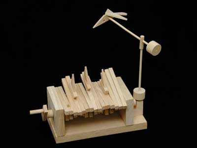
I have this small wooden kit:

90_1315905833.jpg


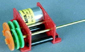
...which I wish to drive/motorise with this 1.5-3V gearbox/motor combination...

95_1315906232.jpg


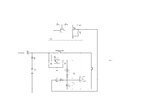
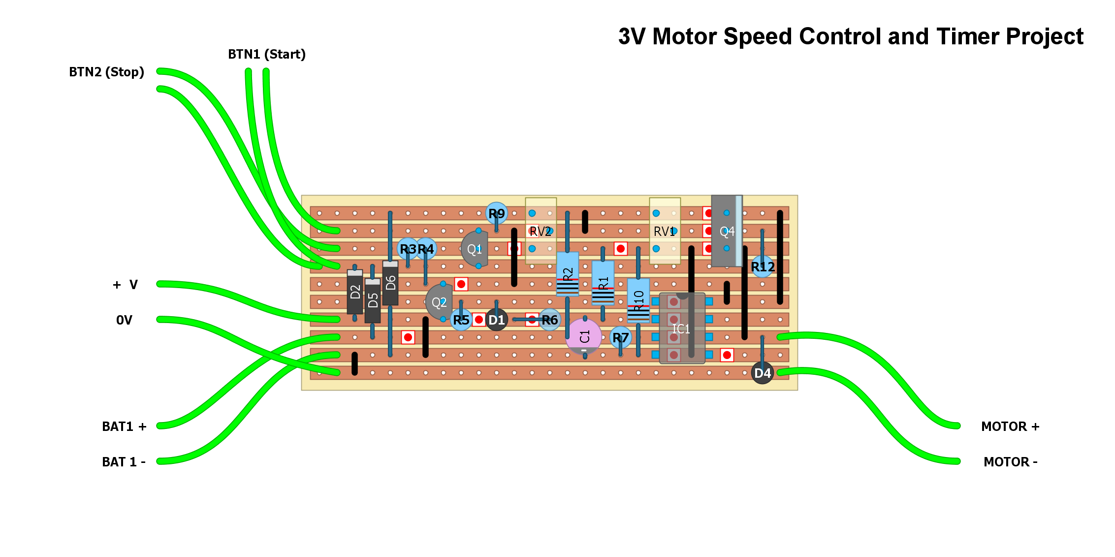
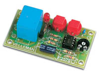
...using a **broken link removed** as a control circuit.

58_1315906482.jpg


Ideally I want to make it battery and mains powered (one or the other, not both at the same time). The idea is that the finshed article will be an idle curiosity that can be started, stopped or will stop on its own after, say, thirty seconds. The reason I want to use a battery of cells is I don't want to have to plug it in.

My problems / questions are as follows:
1. Is there a lower power timer circuit that does the same [exact] job as the one above? I'm trying to keep the number of cells down if possible.
2. The **broken link removed** documentation states that it requires a 12V 'regulated' supply. What does this actually mean? Will it work with eight 1.5V double-A cells?
3. If I use a 12V regulated supply**broken link removed** how would I 'tap' a 1.5V supply for the motor?

I'm sure there will be other questions but I think that's enough for now.

Thanks,

Zulu
 

Hi Zulu,

That looks like such a nice project I couldn't resist knocking up a circuit for you:
motor timer.JPG

Instead of using a 555 timer i have taken a differnet approach using an OP AMP instead, pretty much any will do you should be able to find a DIP package from farnell for around 30p.

The MCP1802-12 is a 1.2V reg. for driving the motor, these are VERY cheap, but not sure if you will find one in a DIP package (only a problem if you are using vera board) you its voltage is slightly lower than the 1.5 you wanted so you could look a similar linear reg (NOTE the use of the shutdown pin).

The latch circuit holds the timer ON once the start btn has been pressed.

RV1 adjust the timer, you might want a 1M instead of 10K?

D1 & R6 quickly discharge the cap once the timer has finished, so you are ready to start again.

D2 & D3 allow you to use 2 different supplies i.e. batteries and power adaptor, Note i have the adaptor voltage set to 9V and the batteries (1.5V x 4) set to 6V, this means that when you are using the power adaptor the batts wont get drained.

this circuit is super low power, and will drop to only the shutdown current of the reg once the timer has stopped, which in this case is 0.01uA! So your batteries wont run flat when your not using it.

Also having a push btn circuit instead of an ON/OFF circuit means you cant leave it ON by mistake (auto OFF).

Connect the motor output to the positive and connect up all the GND's and that should be it.

NOTE: the TVS and diode should be kept close the motor, a 3V TVS should do.

I cant test this circuit, so i hope its ok. If anyone else would like to verify it that would be great.

All the best Chris.
 

Attachments

  • motor timer.JPG
    motor timer.JPG
    394 KB · Views: 98
If this board uses a 555 timer(which were around 20 years ago), it doesn't really need a regulated supply-that chip can run from 5 to 18 volts. The relay is another story, but that's also a pretty forgiving part. (Ideally, it would be better to have a transistor/MOSFET output, but that's a redesign)

If you're using 8 1.5V cells, you could just power the motor from the bottom cell. In other words, one side of the motor connects to common (bottom battery negative), the other side of the motor connects to the relay contact, and the OTHER relay contact would connect to the bottom battery's positive terminal.

Keep us posted. Post a video when you get it working!!
 
Hi Chris,

Well! I didn't expect anyone to go to such lengths with answer to my question! Thank you.
This type of bespoke curcuit design was just what I was getting to all those years ago - and brain v. electronics atrophy has definitely set in!

You're right about finding a V-reg in a DIP package - I've been searching hard for some time now. I only have the capability to use strip-board and surface-mount is definitely beyond me.

I'm continuing to try an source suitable components and I'll let you know how I get on (plus I might have a few questions about drop-in replacements for some of the components you suggested).

Just one question for now - what's the difference between the two circuits - I can see one had a TVS and the other a second switch - but why the difference?

Thanks again,

Zulu
 

Zulu,

No problem, I enjoy helping out on this kind of thing.

I thought I had only posted one schematic, please ignore the one with the extra switch.

I have now created a much better design, just whipped it up this eve, I'm a electronic product designer by day, and tinker with this sort of thing in my spare time.

Before I post the new design, do you have any data for the motor? i.e power requirements?

The new design will allow you to adjust the speed as well, but if you dont want that its just a case of changing a pot for a resistor.

I have chosen all through hole parts for strip-board, and I will post part numbers (dont like to do half a job).

And really this is fun for me, and you wouldn't believe how many circuits I have copied in the past from other peoples generous examples so glad to give a little back :smile:

Chris.
 
Hi Barry,

it doesn't really need a regulated supply-that chip can run from 5 to 18 volts

Yep - I thought that might be the case. If I had no replies here I was just going to go and get the kit and see what happened.

The relay is another story...

Ditto.

...you could just power the motor from the bottom cell.

This I had thought of as well but, as I can't remember all of my stored power theory - is that likely to discharge the 'bottom' cell to a greater extent than the others. How would this affect the output of the whole battery?

I'm currently pursuing Chris' idea but I'm having component sourcing issues and cost is rising (as this is likely to be a one-off and I don't want a pack of four 'whatevers' or the £15 delivery charge because their only in stock in the USA!). Chris is on the case though with a re-design (what a great chap!) so I might give your solution a go if I get stuck.

Thanks for the reply,

Zulu

---------- Post added at 10:15 ---------- Previous post was at 10:03 ----------

Chris,

I thought I had only posted one schematic, please ignore the one with the extra switch.

When I click on the attachment it shows that there are two pages in the one document.

The motor is a 920D/A ASSEMBLED VERSION (RE 280 MOTOR) from MFA/Como Drills. It runs from 1.5V to 3V with a difference in V accounting for the speed increase/decrease. Speed control would be excellent as the gear ratio is adjusted by adding /removing the green gears but this means it's in steps of fixed ratios.

The data sheet for the motor is here - I hope this helps.

Thanks,

Zulu
 

Zulu,

As promised here is the new design:
View attachment motor timer.JPG
View attachment Bill Of Materials For test2.TXT

First off you will notice the battery supply is now 3xAA batteries this is because it now incorporates speed control it is necessary to keep the supply voltage low to avoid over heating issues, the speed control uses Q4 to vary the voltage, its a simple solution, but because its linear the volt drop across Q4 must be kept as small as possible to avoid over heating, R12 is essential by taking some of the demand away from Q4. RV1 is used to adjust the speed (varies volts from 1.5 to 2.5).

U1:A & U1:B are the same component this is a cheap Op amp, U1:B pins 4 & 8 are the same as on U1:A so they are connected.

I have spec'd the mains power supply at 5V (you must not exceed this).

RV2 adjust the timer, min 2 secs to max ?(I haven’t calculated this bit, but at a guess 20mins).
You could replace RV2 for a multi position switch and switch fixed resistor for set timings, using a pot. will make it difficult to know what you are setting.

BTN1 starts the motor running & BTN2 will stop the motor early before the timer does.

I have also attached a full parts list with up to date prices using all through hole components.

This looks expensive, however i have included the battery holder and mains adaptor. Also the Pots are quite pricey, you could choose cheaper ones that require a screwdriver to change.

I have used Farnell for components because in my opinion they have the best component search engine, however they also have a minimum spend of £25, but you dont need to be business to buy from them. If you dont have anything else to buy to make the £25 then you will have to look at maybe Maplin or somewhere like that.

I have simulated the circuit and it seems to work well, however there is no substitute for real world testing, there may be some tweaks needed doing.

Please dont feel you have to use this circuit, as I said its fun for me and if you dont use it someone else might get some tips. But if you do then would love to know how you get on:smile:

Any questions let me know.

All the best Chris.
 
This I had thought of as well but, as I can't remember all of my stored power theory - is that likely to discharge the 'bottom' cell to a greater extent than the others. How would this affect the output of the whole battery?
Yes, you will drain that bottom battery quicker, but it doesn't really look like this is a high-volume product...
 
Hi Chris,

Sorry to be a pain but the image of the circuit diagram when downloaded is only 1.2kb. This makes it impossible to read or print. Could you post it again?

Thanks,

Jack
 

Hi Chris,

The second copy of the circuit diagram was great. Thanks.
I'm a little tied up this week (fitting a kitchen) but I should find time to order the components and make a start on the strip-board layout. The £25 limit at Farnell shouldn't be a problem as I'm going to need some form of enclosure and I'll make up the rest with some lamps for my pinball machine as it's always blowing them. One day I'll get around to the LED upgrade...one day...

More soon,

Thanks again,

Jack
 

Hi Jack,

No problem, keep me posted :smile:
Any probs, let me know.

Chris.

P.S. Love the pinball machine!
 
Hi Chris.

Well, it's taken me some time to get around to the component ordering (the kitchen didn't quite go according to plan and ordinary life stuff gets in the way of hobby time), but it's done now. I have elected to change a few components (switches, battery holder) for astetic and supply issue reasons - I'll publish my differences later.

I'm now setting about designing the layout of the strip-board and came across VeeCAD. I was wondering if the Schematic Editor you used to design the circuit would output a 'netlist' for input to VeeCAD? The formats it supports are here.

This might save me a lot of time and, ultimately, might mitigate the 'human factor'.

Jack
 

Hi Jack,

No probs, here is a tango netlist:
View attachment tango_netlist.TXT

I use proteus (ISIS) for my designs and I'm not familiar with VeeCAD.
I hope it works as tango is the only format that VeeCAD supports which I can export.

I was thinking, before you start on the strip board, it might be prudent to post the schematic in a new thread asking for a design review. This is just incase I have missed something, there are cleverer people than me on here and someone might spot an error which could save time later on.

Regards
Chris
 
Hi Chris,

Thanks for the quick reply.
VeeCAD is looking for a file with a *.net suffix, although it does start processing the *.txt file. However, I get the following error message: 'Tango net list error on line 319: Component BAT1_ has a blank pin name.'
I don't know if this means anything?
Because I'm using VeeCAD's free version it looks like the netlist (the parts that ran before the error) simply adds all the relevent component shapes to the board - in one big pile! As the premium version contains a 'auto-router' I'm guessing that routing will be my next big job. At least VeeCAD should make the task [a little] easier.

Jack
 

you can change the .txt to .net it shouldn't make any difference.

I had a look at the netlist, it looks like it doesn't accept the minus "-" symbol as a valid pin name, try changing the minus symbol to "2" and try again.

Auto routers are over rated, I have laid out dozens of PCB's and never use the auto router.
in your case such a simple circuit won't take long to route.

Chris

P.S.
I just realised, if you are using the netlist for PCB layout then the one I provided has the default footprints for the components, and are probably wrong, I expect the resistors are showing as surface mount not through hole?
Do you need correct package details? or are you using the netlist to re-create the schematic?
 
Hi Chris,

I just realised, if you are using the netlist for PCB layout then the one I provided has the default footprints for the components, and are probably wrong,...

Yes - I thought I'd use VeeCAD to electronically work out the PCB layout. Much easier and user friendly than a pad and pen.

...I expect the resistors are showing as surface mount not through hole?

Actually, there only appear to be about three or four different shapes!

Do you need correct package details?

That would be great - I can't seem to open the libraries of components without using a netlist.

Jack
 

Hi Jack,

Here is a zip file with a new schematic (just changed the battery terminals), a fresh BOM (should be the same) and a new netlist.
View attachment Test2.zip

I have changed the component package details to the correct ones, however there is no guarantee they will work with VeeCAD you may have to change the package types by hand to ones which are compatible with VeeCAD.

Keep me updated:smile:
Chris
 
Hi Chris,

....however there is no guarantee they will work with VeeCAD...

Yep! It didn't - but it was worth a try. I was at least hoping that it would put the component shapes on the board and I could move them around but sadly it just came out with rubbish. Thanks for trying.

They say that every cloud has a silver lining and this one was no exception. I went searching on the net for a similar program and found 'diy-layout-creator'. Check out the results:


What a great bit of kit - just what I needed.

I've just finished this layout and I haven't double-checked it yet - dinner and my failing eyesight dictate that I take a break.

Jack
 

I like that! Really excelent software, its amazing what you can get for free.
 
Status
Not open for further replies.

Part and Inventory Search

Welcome to EDABoard.com

Sponsor

Back
Top