Continue to Site

Welcome to EDAboard.com

Welcome to our site! EDAboard.com is an international Electronics Discussion Forum focused on EDA software, circuits, schematics, books, theory, papers, asic, pld, 8051, DSP, Network, RF, Analog Design, PCB, Service Manuals... and a whole lot more! To participate you need to register. Registration is free. Click here to register now.

Impedance matching in QRP receiver stages

Status
Not open for further replies.

neazoi

Advanced Member level 6
Joined
Jan 5, 2008
Messages
4,122
Helped
13
Reputation
26
Reaction score
15
Trophy points
1,318
Location
Greece
Activity points
36,951
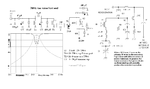
Hello I consider the attached image which is the first stages of a regenerative QRP receiver.
The amplifier comes from another project and output impedange is 50 ohm. The detector assumes an imput impedance of 50 ohm I think as well.
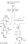
Since I would like to combine these circuits, I would like to migrate the output transformer of the rf amplifier with the input transformer of the detector and use just one transformer.
I am thinking of calculating the inductance of the primary (24turns) of T2 and then calculating the inductance of the secondary of T1.
Then combine them into a single transformer that thas as a primary, the inductance of the primary of T2 and as a secondary, the inductance of the secondary of T1.

In other words, make another transformer that matches the impedance detween the two stages directly, without first converting them to 50 ohm.

Is my approach correct?
(a suitable toroids calculator should be used for calculate the current inductances and make the new transformer)
 

Attachments

  • myqrp.png
    myqrp.png
    13.1 KB · Views: 100

Hello,
This is the migration I refer to.
I have replaced the two transformers to a single one.
It's primary has the same inductance as the primary of the first transformer.
It's secondary has the same inductance as the secondary of the second transformer.

The second transformerinitially used another core material, but I just measured it's inductance and made this inductance with the new core.

Any ideas if what I am doing is right?
 

Attachments

  • Untitled.png
    Untitled.png
    12.8 KB · Views: 93

The modification you did should work fine. The FET LNA with grounded gate should be stable enough for various output impedances.
Perhaps may need to remove (or decrease in value) one of the 22uH inductance's in series with the crystals.
Anyway their inductance values shall be adjusted to get best compromise, frequency stability and frequency tuning range.
 
  • Like
Reactions: neazoi

    neazoi

    Points: 2
    Helpful Answer Positive Rating
The modification you did should work fine. The FET LNA with grounded gate should be stable enough for various output impedances.
Perhaps may need to remove (or decrease in value) one of the 22uH inductance's in series with the crystals.
Anyway their inductance values shall be adjusted to get best compromise, frequency stability and frequency tuning range.

Ok, that is good news!
So in theory any desired impedance "conversion" could be achieved using a transformer, is that right?
So If I have circuits that have different I/O impedances and using transformer coupling, I can impedance match them using this "transformer migration" scheme that I have done in the example above?
 

Transformers converts source power from one voltage and current level, to another voltage and current level, so they can be used for impedance transformation (but only for real part, resistive).
To achieve impedance matching and best power transfer (ignoring losses), the "Turns Ratio" of the transformer is: √ (LoadResistance / SourceResistance)

For example to match a 150 ohms resistive source to 10 ohms resistive load, the "turns ratio" of the transformer should be: √ (10 / 150 = 0.25
So, if the primary have 100 turns, the secondary must have 100 x 0.25 = 25 turns
 
  • Like
Reactions: neazoi

    neazoi

    Points: 2
    Helpful Answer Positive Rating
This is very valuable information for me, thank you!

Nevertheless in my example, I think this calculation of turns ratio is not needed because I assume the author of the circuits has already done it. So to migrate the two transformers into one I just follow the process described earlier?
 

I had a discussion with another member and he said the next:

(reply from member)
I think you're on the right track, but I would just keep the turns ratio the same and not worry about the inductance of each winding. The transformer is resonated, so the inductance doesn't matter that much. If you have 24:4 and 2:10, then I would use 24 to 20 because (24 * 5 / 6 = 20). So you have to use a use 24 to 20 transformer.

There's no guarantee that the output of the amplifier or the input of the receiver is 50 ohms, so it might turn out to be necessary to bridge one side of the transformer with a resistor for stability. Be prepared to add some resistance across one side, something above 1k, for stability. It just depends on the nature of the circuits whether a resistor is needed.


Now, what should I do? Keep the inductance of the secondary of the second transformer the same (in order not to affect the regenerative detector operation), or alter the ratio? I am confused...
 

You can try both situations, and see the results.
Barely mismatch at the output of the LNA would not affect too much its gain or noise figure, which anyway at this receive frequency is not such important.
 

Status
Not open for further replies.

Similar threads

Part and Inventory Search

Welcome to EDABoard.com

Sponsor

Back
Top