arupbsk
Member level 1
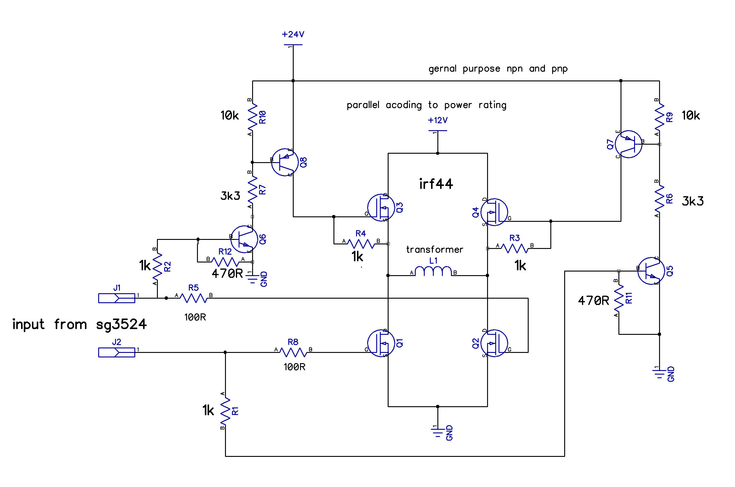
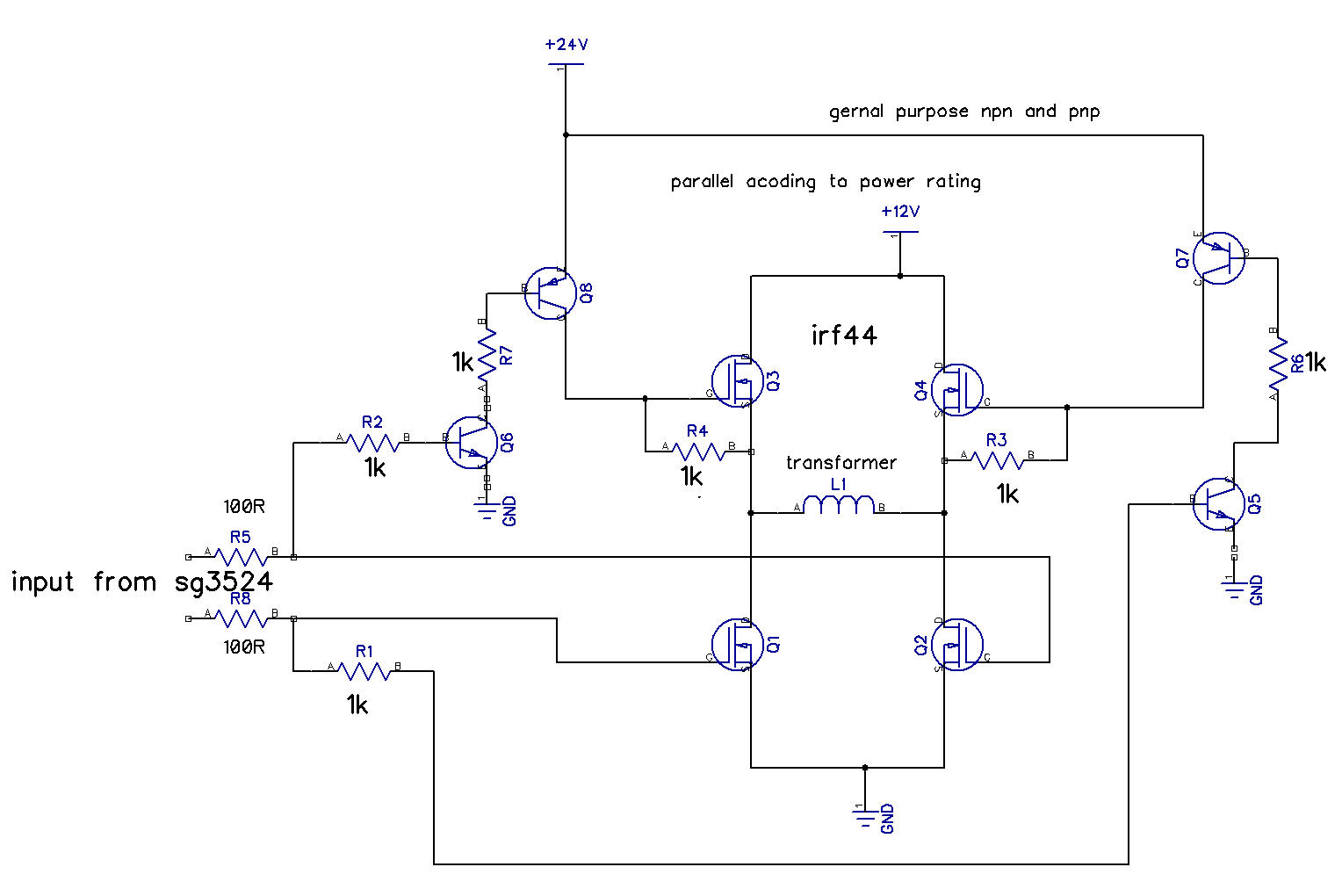
See: http://screensnapr.com/e/EIa8KB.png
I want to ask, if I have a 0-12 transformer in place of a 12-0-12 transformer, can I use the same sg3524 based PWM inverter circuit by just using four Z44 mosfets in place of two by making the transformer lying between H-bridge?
The linked image is for showing the idea. Original design of mine that has a sg3524 has loop from the output to automatically control voltage, etc. I showed the image just for showing how I am planning to connect the H-bridge.
")