Continue to Site

Welcome to EDAboard.com

Welcome to our site! EDAboard.com is an international Electronics Discussion Forum focused on EDA software, circuits, schematics, books, theory, papers, asic, pld, 8051, DSP, Network, RF, Analog Design, PCB, Service Manuals... and a whole lot more! To participate you need to register. Registration is free. Click here to register now.

[Help Required]HFSS Simulation of UWB Antenna Doesn't Tally With Desired Results

Status
Not open for further replies.

frodonet

Member level 2
Joined
Sep 2, 2011
Messages
44
Helped
20
Reputation
40
Reaction score
21
Trophy points
1,288
Activity points
1,636
Hi All,

I'm currently have designed a UWB antenna where UWB stands for (ultra wide band). The problem is that my simulation for VSWR and Gain doesn't tally with the desired results.

Frequency range = 3 - 11.6Ghz

The antenna i'm designing is currently based on a research paper and I have done hundreds simulations using HFSS 11 and i do not get the desired results.

Antenna Desired Properties :
'The measured resultshows that the proposed antenna achieves an impedance bandwidth ranging from 2.9 to over 11.6 GHz and a notched band of 5.0 –5.9 GHz.'

I have also attached my HFSS file designed in HFSS 11 in this thread and it's can be seen below.

Below is my desired VSWR
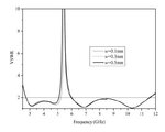
de-vswr.JPG

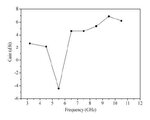
Below is my desired Gain

de-gain.JPG

Below are my simulated results (solution freq = 11.6Ghz)

sim-vswr.JPG

Below are my simulated gain (Theta =0, Phi =90degrees)

sim-gain.JPG

My problem is that I do not get as the desired results...I have set my excitation to lumped port (and tried wave port as well) just that i don't get as close as the desired results.

I followed the HFSS guidance about the 5*w and 4*h for the excitation port but i still do not get the desired results.

I just don't understand where did i went wrong. All the dimension and design are correct and I have run the simulation about 100 times already and still not successful.

Can someone help me on this?
 

Attachments

  • FYP8.rar
    6.5 KB · Views: 173
Last edited:

you will need to post the paper...I believe there is something wrong with your geometry/material properties, etc that is causing your issue (along with several setup issues as well.)

have fun
 

hi dear
what is this? is this an antenna ?
where is your ground?where u saw an antenna with out ground ? notice more in your simulations
 

you will need to post the paper...I believe there is something wrong with your geometry/material properties, etc that is causing your issue (along with several setup issues as well.)

have fun

Hi tallface,

I have attached the original paper at my first post...just under my hfss rar file.

I really would appreciate on some guidance where did i make my mistake.

---------- Post added at 09:40 ---------- Previous post was at 09:38 ----------

hi dear
what is this? is this an antenna ?
where is your ground?where u saw an antenna with out ground ? notice more in your simulations

Hi ferdows,

I assign my substrate bottom face to be an infinite ground plane. Isn't this correct?

I would appreciate if you can point out my mistakes in my simulation.

I am really having headaches after running simulation again and again without getting the desired results.

I have read many forum posts and I just seem to get nowhere at all.
 

hi i attach correct simulation and result
VSWR.JPG
 

Attachments

  • notch UWB.rar
    8.1 KB · Views: 175
hi i attach correct simulation and result
View attachment 61011

OMG...how did you do that?? :shock:

PLEASE TEACH ME!! unbelievable.!!!

Can you help to point out my mistakes?

on another note, can i open your attached file in HFSS 11? because last time i created in another newer version and it couldn't be opened in the older one.

As i am using HFSS 11....

Appreciate for all the help..but i really wnat to understand where did i do wrong ?
 
Last edited:

hi
yes i simulated it in HFSS 11 and if u see u can understand your mistake
 

hi
yes i simulated it in HFSS 11 and if u see u can understand your mistake

Hi ferdows,

Firstly, I want to say thanks for your kind help. I appreciate your kindness.

I saw my mistakes and I would like to raise a few questions.

1. Why is there a need to put a metal at the bottom substrate? I don't understand this at all.

2. Where is the ground located? Because when i check the boundaries, i don see any infinite ground plane...

3. Why the e-field is pointing from bottom to top rather than top to bottom?

4. Why we can use that small size rectangle as a lumped port? What i dont understand about this is that hfss requires us to have at least 5*width of the patch and more than 4*height of the substrate for the port.

5. Regarding the airbox, based on hfss guide, at least more than lamba/4 must be adequate for the radiation. But the airbox must surround all the x-y-z axis?

6. The meshing part as i understand is to provide more accurate simulation. But how did you get your mesh length to be 5.17mm?

7. Can i use theta =0, phi =90 degres just for checking my gain?

Sorry for the numerous questions but I really want to learn about this...
 

hi
1- all magnetic material has 2 pole so we have in antenna 2 pole if we dont have ground so we lost one pole so antenna cant radiation
2-usually ground located under antenna
3-because the radiator is on the top and ground never radiate
4- I dont have idea
5- its related to many things in HFSS usually lambda / 4 is best
6-whats u mean?
7-its related to your antenna pattern
with regard
 

Regarding question 4 above, a lumped port is a specific case of a waveport. The sizing guidelines for the waveport are generally *only* for a microstrip/stripline type of excitation. You actaully *want* the lumped port to be electrically small. The way the port solver interprets a lumped port is that any edge touching a metal object will be defined as metal, while any other edge will be defined as a PMC. Typically, with a square/rectangular lumped port this would set up the two opposite edges as PEC and the other two as PMC, thus exciting a uniform electric field.
 

hi
1- all magnetic material has 2 pole so we have in antenna 2 pole if we dont have ground so we lost one pole so antenna cant radiation
2-usually ground located under antenna
3-because the radiator is on the top and ground never radiate
4- I dont have idea
5- its related to many things in HFSS usually lambda / 4 is best
6-whats u mean?
7-its related to your antenna pattern
with regard

Hi thanks for the clarrifications..

I spent the last 3 hours simulating for the gain...i used theta =0, phi=90..(not sure if this is correct)

this is what i get...it does seem correct for around 5.5Ghz, the gain drops but not sure why it drops more after 6Ghz..maybe my theta and phi is wrong..

how do you know the proper way of simulating gain by the antenna?

Screenshot_1.jpg

I realised that from the paper the gain is in dbi...i don't understand what is dbi as the HFSS don't have that output parameter in dbi...
 

hi
for achieve then gain its better for u to extract 3D pattern and read the highest gain at chart
 

hi
for achieve then gain its better for u to extract 3D pattern and read the highest gain at chart

hi ferdows,

I have to simulate the design and get the results to match the desired results.

But I hope I can get the same simulation results as shown before.

The reason for the gain is that we want to check that at the band notch region which is around 5.5Ghz, that the gain dropped dramatically while the gain increases for other frequencies.

How do one get a dbi simulation in HFSS anywya? :shock:
 

Can anyone help me? how can i simulate the gain properly to achieve the desire results? :sad:
 

I realised that from the paper the gain is in dbi...i don't understand what is dbi as the HFSS don't have that output parameter in dbi...

dbi means gain in dB over an isotropic reference.
The gain in EM simulators is gain over isotropic reference = dbi.
 

dbi means gain in dB over an isotropic reference.
The gain in EM simulators is gain over isotropic reference = dbi.

Then can we use GainTotal to accurately simulate the gain?

But if the VSWR is accurately simulated, how come the gain's simulation results is not close to the desired results?
 

hi
i usually use CST for the gain because HFSS gain related to your radiation box so u need simulated your in every octave
 

Dear Sir,

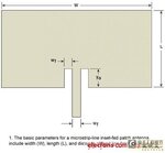
what is the effect of Wf and how can we choose its value ?
thank you.
 

Attachments

  • inset microstrip feed.jpg
    inset microstrip feed.jpg
    20.2 KB · Views: 148

i am doing inset feed so i have a need Wf. please can u explain me. How can i choose that value Wf ?
 

Status
Not open for further replies.

Part and Inventory Search

Welcome to EDABoard.com

Sponsor

Back
Top