Continue to Site

Welcome to EDAboard.com

Welcome to our site! EDAboard.com is an international Electronics Discussion Forum focused on EDA software, circuits, schematics, books, theory, papers, asic, pld, 8051, DSP, Network, RF, Analog Design, PCB, Service Manuals... and a whole lot more! To participate you need to register. Registration is free. Click here to register now.

[SOLVED] Analog Circuit noise problem

Status
Not open for further replies.

lloydi12345

Member level 4
Joined
Aug 31, 2010
Messages
77
Helped
5
Reputation
10
Reaction score
5
Trophy points
1,288
Activity points
1,953
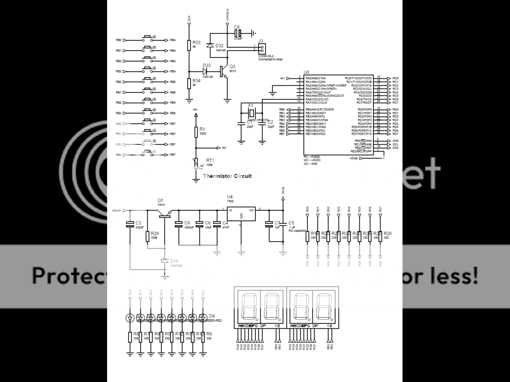
I have made my temperature controller but there's a big problem. With a 320°F setup using a temperature calibrator machine. While my thermistor probe placed inside the callibrator, my controller detects it quite well with a maximum error of 1°F. Sometimes it is 321°F sometimes it is 320°F. Now the problem is that randomly in 15 mins, 30 mins, 40 mins, 1 hour or even two (no particular time really), the temperature display changes to values higher or lower than the real temperature values by 10 values(numbers between 310°F and 330°F). What I'm doing to fix this is to turn off the circuit and turn it on again then everything will go back to normal. I don't think this is right. I think the cause of this is the internal noise but I can't figure out what type or value of capacitor I should add. If it's not the noise then maybe I missed something. I attached my schematic below. C5 is the ceramic cap near the microcontroller.

**broken link removed**

schematic-3.png


Thank you guys.
 
Last edited:

Q3 is driving only the relay right? If so then i don't understand why you have used D33. And why you have used C8 for relay. The relay coil behaves like an inductor. Don't you think that there would be some kind of resonance which affects your signal. Try removing C8 and check.

The switches at left side RB0,RB1 and etc are poorly attached. never leave ports open so they will pick noises. Use pull up/pull down configuration.

Using oscilloscope check if there exist frequency near Al1 port (Use analog oscilloscope), if yes than try adding different values of capacitors and check if frequency is vanished. 0.01microF for higher frequency 0.1microF for mid and 4.7microF for low frequencies. These values are used typically.

Check near regulator if there is some noise frequency. When i connect ADC0808 with NE555 timer of frequency of 200Khz, a frequency also exists at my regulator LM317 which is vanished when i connect 22MicroF capacitor.

Also check noise at Al1 when relay is turned off/ON.

What is the use of R19-R26 resistors?

Why are you using 24Vdc use 12V or 9V power supply and remove Q1. because first its an extra circuit and i know you added it to keep potential difference low so your 7805 wont heat up. Depending on requirement most of the voltage may drop at R29. may be this can also be the reason of your problem.
 

I really appreciate your reply Sajjadkhan.

Q3 is driving only the relay right? If so then i don't understand why you have used D33. And why you have used C8 for relay. The relay coil behaves like an inductor. Don't you think that there would be some kind of resonance which affects your signal. Try removing C8 and check.

The switches at left side RB0,RB1 and etc are poorly attached. never leave ports open so they will pick noises. Use pull up/pull down configuration.

Actually this project was already made by someone and I'm tasked to fix everything. Yes I believe D33 is not needed. Actually, C8 was not yet attached before. I just tried attaching it thinking that it might help a bit since the relay is connected to a power supply.

And for the switches, yes I know it's a poor design but I can't change the board manufactured already and I'm so unfortunate about it.

Using oscilloscope check if there exist frequency near Al1 port (Use analog oscilloscope), if yes than try adding different values of capacitors and check if frequency is vanished. 0.01microF for higher frequency 0.1microF for mid and 4.7microF for low frequencies. These values are used typically.

Check near regulator if there is some noise frequency. When i connect ADC0808 with NE555 timer of frequency of 200Khz, a frequency also exists at my regulator LM317 which is vanished when i connect 22MicroF capacitor.

Also check noise at Al1 when relay is turned off/ON.

I don't have oscilloscope yet. Will a 3 decimal places voltmeter do this job? I've tried using the voltmeter and never seen any fluctuating milli voltage even 1.

What is the use of R19-R26 resistors?

They are used to limit the current produced by the microcontroller going to the 4digit 7segment display.

Why are you using 24Vdc use 12V or 9V power supply and remove Q1. because first its an extra circuit and i know you added it to keep potential difference low so your 7805 wont heat up. Depending on requirement most of the voltage may drop at R29. may be this can also be the reason of your problem.

The design utilizes a fixed 24Vac which is the output of a transformer from the 220Vac socket. The 24Vac was converted to 24Vdc via rectifier diodes (sorry I haven't placed it on the schematic) and used the transistor circuit to limit it near 12vdc.
 

Is it always a 10 degree jump? If so I would suspect a software bug.

Keith
 

Actually this project was already made by someone and I'm tasked to fix everything.
This means you have to check all the possible solution, Keith is right if its always a 10 degree jump then there must be a logical error. Trouble shooting is headache.

I don't have oscilloscope yet. Will a 3 decimal places voltmeter do this job? I've tried using the voltmeter and never seen any fluctuating milli voltage even 1.
No it won't do the job. It measure voltage or current over 100msec of time and it averages the voltage. I don't have oscilloscope yet (I m going to buy used Analog Oscilloscope ) but i have Uni-T UT70A digital multimeter which can measure frequency up to 10MHZ. Try buying one of those...they are the cheapest and best budget price.

The design utilizes a fixed 24Vac which is the output of a transformer from the 220Vac socket. The 24Vac was converted to 24Vdc via rectifier diodes (sorry I haven't placed it on the schematic) and used the transistor circuit to limit it near 12vdc.
I believe that you can replace the transformer, its not that hard.

First look for what keith said. If not then try making the simplest circuit needed on breadboard. i.e. controller, display and temperature sensor. I believe it will work. If programing code is not yours then try writing a simplest code to do your job.
I never liked thermistors, they are cheap but i don't know how to evaluate 3 constants of its equation. But i do know its relation with temperature is not linear so ADC quantization will also be nonlinear. LM35 is the simplest.
 

Is it always a 10 degree jump? If so I would suspect a software bug.

Keith

No, it's not always a 10 degree jump. Example is 320 then 321 then 319 then 321 then 320 sometimes 317, 318 and so on. I believe it's not in the software because I was able to simulate it in proteus. Using a resistor instead of the thermistor and changing its value for the corresponding temperature it displays the right temperature on LCD. I was able to linearize it using the Steinhart-hartz equation.

This means you have to check all the possible solution, Keith is right if its always a 10 degree jump then there must be a logical error. Trouble shooting is headache.

No it won't do the job. It measure voltage or current over 100msec of time and it averages the voltage. I don't have oscilloscope yet (I m going to buy used Analog Oscilloscope ) but i have Uni-T UT70A digital multimeter which can measure frequency up to 10MHZ. Try buying one of those...they are the cheapest and best budget price.

I believe that you can replace the transformer, its not that hard.

This project is actually designated for the fryers supplied on us. The fryers have their own 24vac transformer so I need to convert it to dc using a rectifier diode. I used to hate thermistors because it took me weeks to linearize them trying lots of circuits using operational amplifiers and trying lots of codes but everything went good when I focused in the software. It gave me 1deg F tolerance. I've seen little voltages on my analog ground and digital ground. I attached my voltmeter's + lead to the ground of C9, - lead to the ground of my analog circuit and I saw 40mV changing rapidly until 60mV. I've seen it changing a lot when the relay is turned on or when it is turned off. I tried switching the controller off then the small voltage reading vanished. I turned it on then from 1mV it starts to increase everytime the relay functions. When the voltage in the ground reaches 4mV the temperature starts to malfunction by 1 degree temperature fluctuation. As the mV increases the temperature reading also increases its errors.

So do you think my current enemy is noise??
 
Last edited:

This project is actually designated for the fryers supplied on us. The fryers have their own 24vac transformer so I need to convert it to dc using a rectifier diode.

Ok if this is a restriction. But still Q1 is a worst solution you have done and i am not ok with it. I think your current requirement is not that much. Try using 7805 without Q1.To make current more less from 7805 don't use your controller to drive 7segments, instead use ULN2003. It has 7 drlington pairs, so 4 ICs will do the Job and its quite cheap. Connect your 24V supply to common of You display and attache all the pins of the display to ULN2003 Collector side using calculated resistors values in series of each collector.

Another way is to Replace Q1 with PNP. Emitter connects to 24V and base to ground using a base resistor and collector to your regulator. Put a zener of 10V+ in series to emitter. Zener rating will be according to you current requirement. Choose a base resistor value so that your Q1 is always in saturation.

This is the first thing you have to deal with, the rest are the later problems. As you are troubleshooting so you have to start from start of circuit.

You need to do some effort lloydi12345, Assuming problems and their solution will waste much of your time. Try to put the simplest form of your circuit on the breadboard and see whats going on.

use a 12V AC transformer without using your relay part. then look if it is measuring accurately. If so then add relay part and check again for half an hour if its working fine. If yes then add the switches according to schematic and see again. If still working fine then replace power supply as you used in schematic.If still ok then you are have bad wiring issues like bad ground and like wise. Take these steps and You will find your answer.

And yes one more thing just came in my mind. Before doing all that make all the seven segment glow and see if 7805 still gives 5V? because Ib=[24-0.7]/100k = 233micro Amp. Max hfe or beta for your Q1 is 50 so 50xIb =11.65mA which is far less for you circuit. Try replacing your R29 with 1K -1.2k.
 

Or maybe you could use a MOSFET instead of BJT? I mean some kind of low power one suitable for driving with 5v directly from uC.
 

Or maybe you could use a MOSFET instead of BJT? I mean some kind of low power one suitable for driving with 5v directly from uC.

Why are we inserting mosfet then why not to put a power zener in series with 7805. I am not in favor in Q1 because 1st its an extra component, 2nd heat generated by both of them would be equal to single 7805. He should try using 7805 directly to see if his circuit works fine and how much do the regulator heats up.
 

What language do you use for programming uC?

I've read somewhere that it's possible to make a blooper ina code, which results in stack overflowing after a long time of operation. Let's say that you have some interrupt being invoked every second. As a reaction to interrupt you push 3 values on stack and remove 2 values. That gives you 1 byte (or word or whatever) of space being taken from stack permanently. As this is relatively slow process and stack capacity is rather large it can result in strange behaviours after a long time.

I think I've done that once in AVR micro. IIRC it was starting to act bizarre after some 20 hours of operation or so (but it was a lower power app generally not doing anything most of the time).

I can't say for sure, but that's actually the only reason i can think of that would make processor act strange after a long period of time.


Another thing: did you notice only increase of the reading or also decrease? If you noticed decrease after a similar amount of time that could mean some resonant effect of very very low frequency (1/1.5h? i mean like 0.0002 Hz?)
 

Poorchava, not only the temperature increases but it also decreases. The programming language I used here was Mikrobasic.

Sajjadkhan, I'm thankful you're still concerned about the progress of my problem. I forgot to say that I'm averaging up 5 temperatures since I don't like to see temperatures jumping. With these there should be no temperature jumps since they are averaged. If I removed my averaging software routine during the time that the circuit becomes unstable and the temperature jumps with large values, I guess the temperature jumps will be even higher like by 20 degrees.

Well what I did was measured the resistances of the thermistor at different temperature settings. I wrote then the measurements in a table. I'm thinking that the heater calibrator might caused the problem so I didn't used it for a while. I then looked for resistor values on the table which has its desired temperature and connected it directly to the slot where the thermistor connector is connected. I don't know what happened next but it went good. First, I turned off the circuit then afterwards I waited for the temperature to fluctuate again. I tried shorting the ground of the analog circuit to the ground directly produced by the rectifier diode. The milli voltages accumulated to 60mV then disappeared because it was shorted. The temperature having large errors very slowly decreased until it reached the right temperature. I don't know if the issue is all about the analog ground and the digital ground thing but everything went good. I've seen from other threads that they separated the analog ground from the digital ground but what I did was combined all the grounds thinking that there might be something that acted as a resistance between all those grounds. Although sometimes in no time the temperature shown still increases by 1 degree, after a while it goes back to the proper temperature I guess this would be the best solution for me now.
 

Your circuit is very compact so there should not be any noise as you are not using any long wire.

ok here is what you can do in your existing circuit. Replace r29 by 2Kohms. after that replace thermistor by a 10K multi-turn variable resistor i.e. one upper one pin to 5v mid pin to adc and lower pin to ground....see if the error still exist. do this without averaging. You can do this just within an hour....Do it and let me know. We are going to catch the error from its root :)

Talking about Analog ground... if you find voltage across any two analog ground then its a poor wiring or poor PCB track. Try to coat it with solder.

Talking about digital ground, they have a limit to sink current and if you are injecting more current then there would be a voltage drop and its not good for the chip.

And yea post a picture of your hardware based circuit,front view and back side in good resolution.
 

Sajjadkhan, I'm thankful you're still concerned about the progress of my problem. I forgot to say that I'm averaging up 5 temperatures since I don't like to see temperatures jumping. With these there should be no temperature jumps since they are averaged. If I removed my averaging software routine during the time that the circuit becomes unstable and the temperature jumps with large values, I guess the temperature jumps will be even higher like by 20 degrees.

I was working before voltage measurement using ADC and I experienced unstable result and fluctuating but all came goodby averaging by 10 and i got more stable results without any changes in my hardware..
 

I was working before voltage measurement using ADC and I experienced unstable result and fluctuating but all came goodby averaging by 10 and i got more stable results without any changes in my hardware..

I'm also thinking about this idea but this would take a lot of time to measure the temperature if I started from 90 deg F to 350 deg F. I'm required to get the temperature in less than a minute only.

Your circuit is very compact so there should not be any noise as you are not using any long wire.

ok here is what you can do in your existing circuit. Replace r29 by 2Kohms. after that replace thermistor by a 10K multi-turn variable resistor i.e. one upper one pin to 5v mid pin to adc and lower pin to ground....see if the error still exist. do this without averaging. You can do this just within an hour....Do it and let me know. We are going to catch the error from its root :)

Talking about Analog ground... if you find voltage across any two analog ground then its a poor wiring or poor PCB track. Try to coat it with solder.

Talking about digital ground, they have a limit to sink current and if you are injecting more current then there would be a voltage drop and its not good for the chip.

And yea post a picture of your hardware based circuit,front view and back side in good resolution.

Sajjadkhan, I guess the problem is already on the way the PCB was built. The hardware is already messy and it is already a year old. I've seen lots of thermal paste scattered and the previous maker of this board sprayed a PCB varnish which might be the cause of poor connections. I'm only assigned to fix the board and not to create another so I can't do any better design yet.

The noise comes from the 24vdc relay when turned on and off.

I'll try your resistor mod suggestion if the problem occurs for a longer time, but for now I can't make any changes since I'm asked already to test it with the fryer. Thanks a lot.
 

The noise comes from the 24vdc relay when turned on and off.

how did you know that the relay cause the noise?

I have the same connection before a bunch of relay and a controller but there is no noise happen.. try connecting the supply of your relay just after the 5v output of your regulator and of course you need to use 5v relay or 6v will do..
 

Averaging may or may not work if all the wrong values are averaged then what? I do average just for ADC own internal error or if the signal is varying. If there is noise then try to remove the noise.

Yes even i think relay is not a problem. and yes just put a 22microF capacitor at 5V output to be sure.
 

how did you know that the relay cause the noise?

I have the same connection before a bunch of relay and a controller but there is no noise happen.. try connecting the supply of your relay just after the 5v output of your regulator and of course you need to use 5v relay or 6v will do..

I knew it was the relay because when the relay was disconnected last time from the circuit everything worked with no errors. I'm using a relay powered by 24vdc.

Averaging may or may not work if all the wrong values are averaged then what? I do average just for ADC own internal error or if the signal is varying. If there is noise then try to remove the noise.

Yes even i think relay is not a problem. and yes just put a 22microF capacitor at 5V output to be sure.

I already tried 22uF at the output of 7805 before. Didn't gave a dime actually.
 

have you already tried using 6v/5v relay and get the supply to your 7805 regulator?
how often your relay to be on and off? hmmm
 

Actually his circuit is demanding much current and he is providing it not enough. Its just like if i make you breath through a very small diameter pipe and ask you to think. you wont be able to think.

Assuming his wiring is good, his Q1 circuit is not working.

The diode D18 minimum required current is 0.25mA and he is providing it exactly the same. Its not how the zener works. You should provide it enough current so that when current is entering the base of Q1 the zener is still on. The current you are providing is two low that only turns on the zener, you circuit requires more current.

Zener rated voltage is given at test current i.e. Izt which is 21mA and ur circuit consumes less than 800mA. 800mA/50 =16mA where 50 is the max beta of your Q1. so in total you need to provide 16mA + 21mA = 37mA at the base of Q1. [24-0.7]/37mA =630 ohms. This is the required value of R29.

Now this is what is happening,actually 2 things are happening: You current is too low so 1st thing is that when your circuit is turned on, zener is turned off. so there is no converting down to 12v. 2nd you circuit is running fine and when relay turns on it requires more current which is taken away from your PIC and your pic starts behaving abnormal and gives you arbitrary values.

Now fix R29 with 630 ohms which should be of 1 Watt resistor. This is the only problem why aren't you doing it. Give us your feed back.
 
Status
Not open for further replies.

Similar threads

Part and Inventory Search

Welcome to EDABoard.com

Sponsor

Back
Top