Continue to Site

Welcome to EDAboard.com

Welcome to our site! EDAboard.com is an international Electronics Discussion Forum focused on EDA software, circuits, schematics, books, theory, papers, asic, pld, 8051, DSP, Network, RF, Analog Design, PCB, Service Manuals... and a whole lot more! To participate you need to register. Registration is free. Click here to register now.

555 is not working for 50% duty cycle in real time but working on protious........

Status
Not open for further replies.

aliraza786

Full Member level 4
Joined
Nov 10, 2009
Messages
210
Helped
14
Reputation
28
Reaction score
14
Trophy points
1,298
Location
Lahore, Pakistan, Pakistan
Activity points
2,914
hello i am using this circuit for almost 50% duty cycle but this is working on protious but not in real time i change 3 555 but the problem coudnt solve...i worked a lot on 555 but i am not succed in finding the problem......... cats.jpg
 

The resistance ratio is incorrect. It's not guaranteed to trigger the lower threshold.
 

Alex i join the circuit like in the link but still no output....:(....
and FVM i want to generate 6khz frequency i calculate these values from a software named 555 timer ...but these values working on protious but not in real time please suggest me how can i change the values...
or calculate from the formula but the problem is my calculated values cant found in my lab thats why i use online calculator or 555 software to calulte the values which i found easily.....thnks.....
 

Also your current resistor ratio gives (10K+4K7)/(10K+(2*4K7))=75.7%
to get close to 50% you have to use an R1 much higher than R2 (resistors as shown in your schematic)

Alex
 

pins 6 and 7 are connected to the resistors reversed
This is intentionally for the 50% duty cycle circuit, figure 14 in the National datasheet. However, the datasheet also says:
Note that this circuit will not oscillate if RB is greater than 1/2 RA because the junction of RA and RB cannot bring pin 2
down to 1/3 VCC and trigger the lower comparator.
In the present circuit, RB is about 0.5 RA, so considering a threshold tolerance, it won't necessarily work.

Personally, I prefer a more simple 50% circuit with a single timing resistor feedback from output pin to pin 2/6.
 
I wasn't aware of that configuration, I have used the 555 a few times and I was using the classic configuration

Thank you
Alex
 

Personally, I prefer a more simple 50% circuit with a single timing resistor feedback from output pin to pin 2/6.

That method has been criticized by Paisley (**broken link removed**) as not being particularly accurate.* As I recall, but can't find the reference right now, it does work better with the CMOS chip.

John

*You need to scroll about half-way down the page to the 50% circuits.
 

Alex i join the circuit like in the link but still no output....:(....

The described schematic works fine for me and in that article also explains the equations to calculate the frequency and duty ratio.

Alex
 

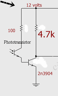
i have to design a circuit name 2 channle ir remote controle so i convert the frequency to voltage through LM331 and compre the out put voltage by comparator everything works fine but the problem is when i connect the 555 output pin to lm331 input pin everything works fine but when i transmit the frequnecy through ir led and attach ir reciver at the lm331 frequency input then nothing happpened this means that the problem is with ir reciver..........i use universal ir reciver see the picture attach.......i dnt know the error is due to the frequency response limitation of the transistor or anything else..........
53_1314251926.gif


is ther any frequency limitation in this circuit..??
 
Last edited:

Status
Not open for further replies.

Part and Inventory Search

Welcome to EDABoard.com

Sponsor

Back
Top