bicave
Full Member level 1
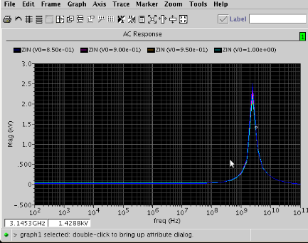
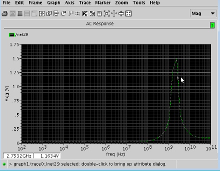
When checking AC response of bandpass filter look perfectly, put VAC=1, VDC=V0 ( suitable Bias for operating).
But when I apply transient simulation the output unstable.
what will happen if
1. changing size of Min?
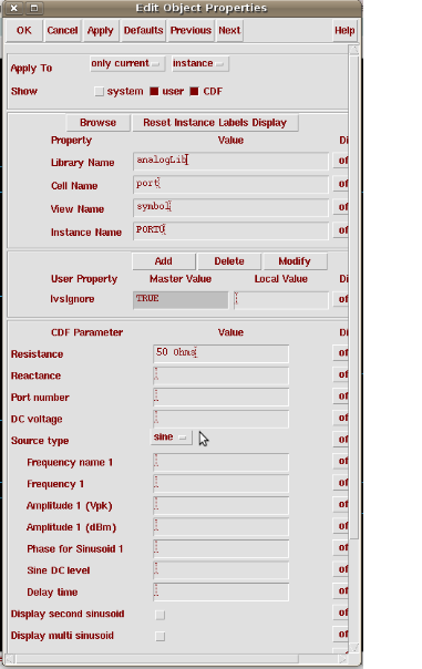
2. Change Ib at buffer how big is it good.
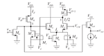
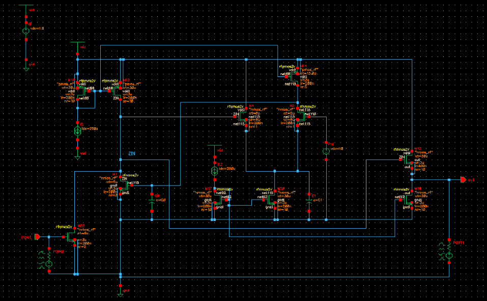
Pls see attached file.
But when I apply transient simulation the output unstable.
what will happen if
1. changing size of Min?
2. Change Ib at buffer how big is it good.
Pls see attached file.