Continue to Site

Welcome to EDAboard.com

Welcome to our site! EDAboard.com is an international Electronics Discussion Forum focused on EDA software, circuits, schematics, books, theory, papers, asic, pld, 8051, DSP, Network, RF, Analog Design, PCB, Service Manuals... and a whole lot more! To participate you need to register. Registration is free. Click here to register now.

Problems writing registers to AD7793

Status
Not open for further replies.

fjmurcia

Newbie level 3
Joined
Aug 17, 2011
Messages
3
Helped
0
Reputation
0
Reaction score
0
Trophy points
1,281
Activity points
1,306
We are developing a board for remote monitoring using MSP430 and AD7793. We are able to read the values from the AD converter without problem but we cannot write the gain value in the registers in order to modify the input range.

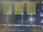
I have attached one screenshot from the oscilloscope where the yellow signal is SCLK and the blue one is DIN (data inserted into the AD). As you can see in the attachment, we are trying to write the following secuence: 0x10, 0x01, 0x10 in order to write the first 8 bits to the communication register and the following 16bits to the configuration register (gain=2 and buffered mode).

If you or your team have some experience similar to this I will appreciate some help, thank you!
osc_spi (Medium).jpg
 

We have to assume, that nCS is controlled correctly. Then the wequence should write to the configuration register. The sequence seems to be however 0x10, 0x02, 0x10, and thus set gain=4.
 
Thank you for your response.

We are activating CS at the beginning of the process and we never deactivate it. We are working with the CS as if it was hardwired to GND (we read this from datasheet)
 

When not operating CS, you have to care not to lose synchronization. We can't see from your waveforms, if the device is synchronized.
 

Thank you again for your reply. We have finally solved this problem by writing 32bits sequence before each operation.

Now we have some accuracy problem. For example, we measure with our calibrated multimeter 45,80mV but the code obtained from AD7793 (indeed the mean of 50 codes) is 49.90mV. We have this problem no matter the gain used.

We are trying full-scale calibration, zero calibration... all the possible ways but we always obtain this apparent offset between the "real" voltage and the converted voltage... any hint?
 

We have finally solved this problem by writing 32bits sequence before each operation.
In other words, missing synchronization has been somehow the problem.

For example, we measure with our calibrated multimeter 45,80mV but the code obtained from AD7793 (indeed the mean of 50 codes) is 49.90mV.
If the problem persists after calibration, I suspect a software error, or severe non-linearity. I would check linearity with a set of measurements first.
 
Status
Not open for further replies.

Similar threads

Part and Inventory Search

Welcome to EDABoard.com

Sponsor

Back
Top