Continue to Site

Welcome to EDAboard.com

Welcome to our site! EDAboard.com is an international Electronics Discussion Forum focused on EDA software, circuits, schematics, books, theory, papers, asic, pld, 8051, DSP, Network, RF, Analog Design, PCB, Service Manuals... and a whole lot more! To participate you need to register. Registration is free. Click here to register now.

simulation result from schematic does not match with that from momentum in ADS

Status
Not open for further replies.

Julian18

Full Member level 3
Joined
Apr 9, 2007
Messages
167
Helped
5
Reputation
10
Reaction score
5
Trophy points
1,298
Activity points
2,389
Hi: everybody

I am trying to simulate and design a matching circuit of PA in ADS environment. The procedure I am following is this
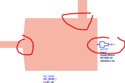
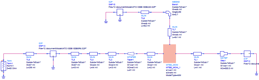
firstly I simulate the schematic using MLIN, Term,MTAPER etc. ( and S2P if needed), also I put MSTEP here and there to cope with the step effect. Being aware of the fact that using MTEE is range limited, I create My own MTEE_MOM in momentum, the schematic is shown below:
99_1313584013.png
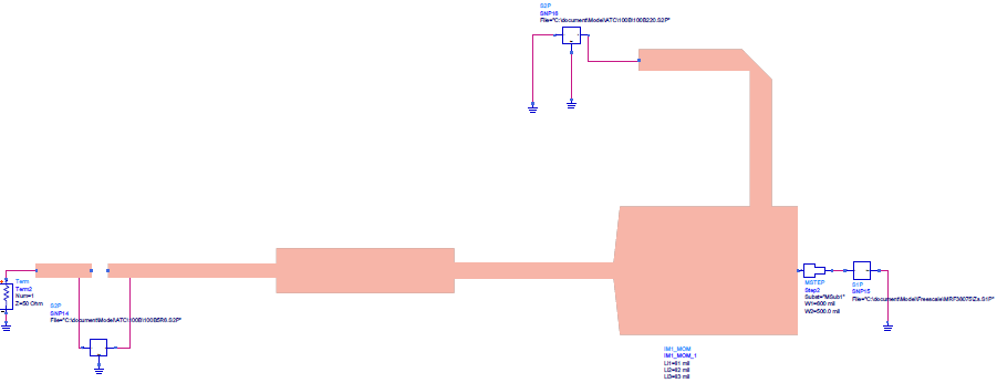
then I generated the corresponding layout and simulated using momentum (circuit shown below)
74_1313584389.png
Since I have done a lot of work in generating my schematic to emulate the real layout I expected these two results should match to some degree.simulation results shown below:
97_1313584882.png
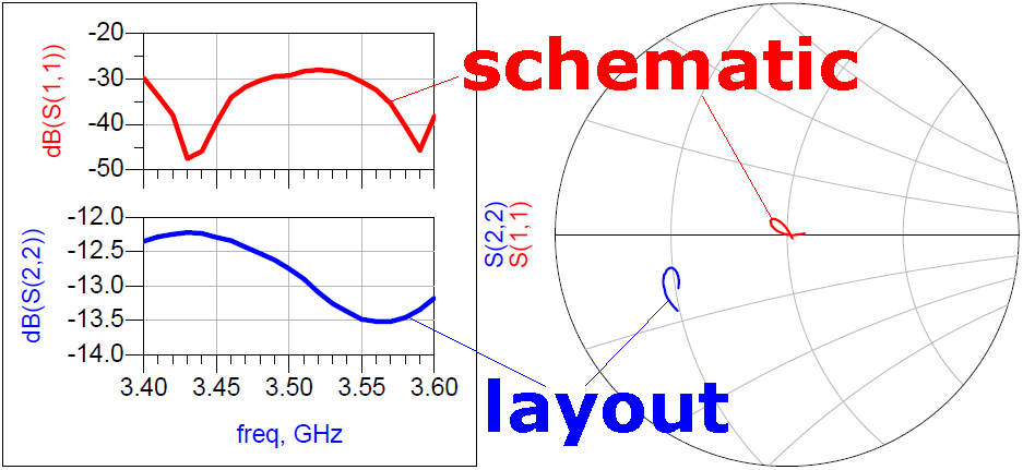
they are matched, only in shape, in smith chart, but the reflection result generated by momentum is order of magnitude large than the one from schematic.

So My questions are:
Should these two results match to each other (to some extent) if we carefully prepare our schematic?
if Yes, How can I do to make them match?
if the answer to first question is No, then, how to do matching of filter design? using EM simulation directed? then these ADS microstrip components are worth nothing?


Thanks

Julian
 
Last edited:

I always use schematic simulation first, then simulation the momentum simulation, and do some modifications at momentum simulation.
 
Hi tony:
so you must have compared your schematic simulation results and the initial momentum results, are they match to each other?
 

Using schematic components is good for a 1st order approximation of a circuit, especially a real, metal layout. The schematic doesn't take any component interactions into account, so it's accuracy is already limited. However, simulation, tuning and optimization from a schematic-based design are VERY fast because the elements have closed-form solutions that are super-fast to calculate.

Once you get a good design from schematic, I move it to a layout and run Momentum on it. Almost guaranteed, the schematic and MoM results will not line up much at all If you're lucky, similar shape, but generally off in frequency and loss). Momentum takes EVERY interaction of EVERY piece of metal into account. It is the most accurate to reality that you will get between the two options. Once you have a layout that is close, you simply start tweaking the layout and re-running Momentum until you hit the sweet-spot with your design. Don't forget you can further refine your Momentum model by turning on Edge Mesh (better estimation of edge-coupling effects) and using Thick Metal models (better estimate of losses). Both will increase your simulation time, so start with a thin-metal model and no edge-mesh, initially, then add them later to tweak your design into it's "final" configuration.
 

then these ADS microstrip components are worth nothing?

Your discontinuities and line shapes are somewhat extreme, so that the circuit models are not very accurate for your case.
Some combination of circuits models for normal line segments and EM model for the discontinuities is indeed more accurate.

Looking at your EM T-junction in the upper schematic, it is not clear if the ports have the proper width of the lines/devices that are connected there.

Yeah, i use parameterized momentum component, so that the width of MTEE section will always be the same as that of the MLIN's connected to it.
Thanks.
 

Yeah, i use parameterized momentum component, so that the width of MTEE section will always be the same as that of the MLIN's connected to it.
Thanks.

I would double check that your Momentum ports are simulated with the small terminal width of the connected line. This will be much more accurate than cascading the external step/tapers.

35_1313655339.png
 
Last edited:

Status
Not open for further replies.

Part and Inventory Search

Welcome to EDABoard.com

Sponsor

Back
Top