Welcome to our site! EDAboard.com is an international Electronics Discussion Forum focused on EDA software, circuits, schematics, books, theory, papers, asic, pld, 8051, DSP, Network, RF, Analog Design, PCB, Service Manuals... and a whole lot more! To participate you need to register. Registration is free. Click here to register now.
I hope I understand you well. Measure/determine the input voltage range that you require to get the desired duty cycle at the output.
Now you can make a three resistor series circuit from ground to supply voltage. The middle resistor will be the potentiometer, the potentiometer's wiper goes to the input of the PWM circuit. You should choose the upper and lower resistor in such a way that you get the required input voltage range. Make sure the current through the potentiometer is large with respect to the input bias current for the PWM circuit.
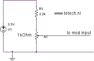
hello friend thank you i came to know about a good pulse width modulator with your post. you have to use two pots one for varying duty cycle and other for varying frequency. you didnt told at what voltage you want to operate. i suppose it as 3V and you have to connect 2K ohm resistor plus 1k ohm potentiometer and 100 ohm resistor in series between +VCC and Gnd. Now connect the tap of the potentiometer to MOD PIN to vary duty cycle (voltage at mod pin varry from 0.9v to 0.1 v to produce a duty cycle change from 0 to 100%)
to change the frequency you have to take one 500k ohm pot and make it short two terminals out off three terminals, finally you have to connect 500k ohm pot and 50K ohm pot in series between SET pin and Gnd. the maximum resistance value allowable between set pin and Gnd is 50K ohm to 800K ohm. so you can increase pot vaue up to 800K ohm.
I hope I understand you well. Measure/determine the input voltage range that you require to get the desired duty cycle at the output.
Now you can make a three resistor series circuit from ground to supply voltage. The middle resistor will be the potentiometer, the potentiometer's wiper goes to the input of the PWM circuit. You should choose the upper and lower resistor in such a way that you get the required input voltage range. Make sure the current through the potentiometer is large with respect to the input bias current for the PWM circuit.
Thanks for your answers. I am new with PWM or potentiometer, Actually I am very new in Power electronics. I am trying to do something myself. In this circuit the voltage range will be between 0-1 V . Firstly I removed the PWL voltage. and then connected 1 k potentiometer resistance to MOD, then I connected one 2k and one 100 ohm upward direction and connected the middle of this the other terminal of 1k resistance. Then I connected 2k resistor to ground and 100 ohm to "-" part of voltage. But It is not working or I understood wrong ( Please can you reveal on image?
---------- Post added at 11:31 ---------- Previous post was at 11:21 ----------
And I have an other question what is the relation between Mod voltage and duty cycle?
---------- Post added at 11:31 ---------- Previous post was at 11:31 ----------
And I have an other question what is the relation between Mod voltage and duty cycle?
This site uses cookies to help personalise content, tailor your experience and to keep you logged in if you register.
By continuing to use this site, you are consenting to our use of cookies.

 ( Please can you reveal on image?