Continue to Site

Welcome to EDAboard.com

Welcome to our site! EDAboard.com is an international Electronics Discussion Forum focused on EDA software, circuits, schematics, books, theory, papers, asic, pld, 8051, DSP, Network, RF, Analog Design, PCB, Service Manuals... and a whole lot more! To participate you need to register. Registration is free. Click here to register now.

Two ways to test the linearity of a Switched Capacitor Integrator? Which is better?

Status
Not open for further replies.

sharezhao

Junior Member level 1
Joined
Jun 12, 2007
Messages
17
Helped
0
Reputation
0
Reaction score
0
Trophy points
1,281
Activity points
1,409
Dear all:

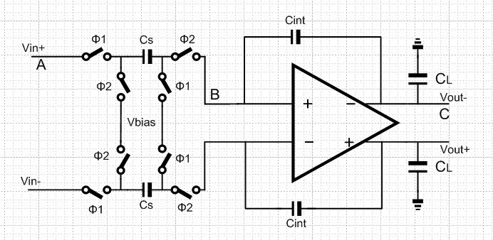
The switched capacitor integrator is as following. how to test the linearity of the integrator? I am considering to do it in following way.

1) Input is a pure sin wave, the do pss+pac, then calculate the iip3

2) input is a pure sin wave, the output is a stair-case sin wave, then sample the output and do DFT the watch the HD3.

Which way is better? Anyone watch this post must leave you idea. LoL!!

Thank you for your attention!!!


sharezao,

It depends on the purpose of the integrator
If you develop a sigma delta ADC (for example), the linearity of the output is estimated from the spectrum.
If the integrator is a component of the RF-path, the first way of simulation can take place.
 

sharezao,

It depends on the purpose of the integrator
If you develop a sigma delta ADC (for example), the linearity of the output is estimated from the spectrum.
If the integrator is a component of the RF-path, the first way of simulation can take place.

AlexVD;

Thank you for your reply.

I used this integrator in 4th switched capacitor filter. I used the second way the evaluated the performance. But find that the transient analysis is not accurate enough, because I do DFT with the ideal sine wave with conservative accuracy some time I can only achieve around -110dB HD3. So I guess the former one will be more accurate. What do you say?

Best Regards
 

sharezao,
Try to change analog options for simulation such as reltol and abstol. Also you can decrease time step.
Best reguards
 
I used this integrator in 4th switched capacitor filter. I used the second way the evaluated the performance. But find that the transient analysis is not accurate enough, because I do DFT with the ideal sine wave with conservative accuracy some time I can only achieve around -110dB HD3. So I guess the former one will be more accurate. What do you say?
Best Regards

Hi sharezhao,

I suppose by saying "test" (your 1st posting) you mean "simulation", correct?
What means "tran analysis is not accurate enough"? What is your alternative?
By the way: The existence of harmonics - in your case - is not a matter of linearity. Don't forget, you have no time-continuous signal. That means, the majority of harmonics is due to the staircase character of the signal.

LvW:
YEAH, I mean simulation. My another way is to PSS analysis to see my IIP3 point. By the way, I think you are right, the stair case is not like contniuous signal. I'm working on signal and system right now to see what's really going on with this circuit. Thank you for your advice.
 

Status
Not open for further replies.

Part and Inventory Search

Welcome to EDABoard.com

Sponsor

Back
Top