Continue to Site

Welcome to EDAboard.com

Welcome to our site! EDAboard.com is an international Electronics Discussion Forum focused on EDA software, circuits, schematics, books, theory, papers, asic, pld, 8051, DSP, Network, RF, Analog Design, PCB, Service Manuals... and a whole lot more! To participate you need to register. Registration is free. Click here to register now.

Looking for low cost, low power parts for H-Bridge solution.

Status
Not open for further replies.

JoKKeR

Full Member level 2
Joined
Feb 14, 2008
Messages
130
Helped
2
Reputation
4
Reaction score
2
Trophy points
1,298
Location
Estonia
Activity points
2,281
Hi!

I have low power DC motor. Full load at 15V is under 200mA.

Signals are coming from MCU.


Atm im liking 2x IRF7105. 1P and 1N type MOSFET array. ~0,5 EUR per part. The problem is that it is avalable only surface mount type.
IRF7105 datasheet: http://letsmakerobots.com/files/IRF7105.pdf

H bridge.JPG
Probably i do not need drivers.

Thank you in advance!
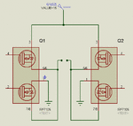
 

First problem is that you have the Pmosfers and Nmosfets inverted, and also the output is not the drain as it should be.
The correct configuration is like

IRF7105_bridge.gif

The second problem is that you have to control the gates independently to be able to apply a dead time.
The dead time is needed because it takes some time for the mosfet that is on to turn off and you must wait before you turn on the other mosfet in the same side or you will create a short circuit with both mosfets conducting.

Alex
 
Last edited:
alexan_e, Thank you!

I appreciate your fix on problem that i never bothered to notice.

H bridge. v2JPG.JPG

It is late atm, so i didnt give it much thought... by your way... by simply re-wiring circuit, now i can add delay_ms(1) to fix issue with moment of short circuit effect. Of it means that most likely i need to use 4 pins for H bride signal?

The signals are very rare. Max period is around 300ms. I like very simple solution that works just to rotate the motor.

Again, Thank you!
 

When you connect the two gates together then you have two states , 0=P mosfet on and 15v=Nmosfet on but there is no state where both mosfets are off and this is the state that you need to apply the deadtime, the delay will not help if you have a common gate connection

Turn P on
Turn both off
Turn N on
Turn both off

Alex
 

Thank you once more!

OK, now i believe that i do understand the core of this problem. How bad this short circuit could be? Can i find a simpler solution like applying capacitor to delay signal? OR i do need 2xP and 2xN part?
I promise that i will think it true later.
 

I haven't experimented with common drive solutions so I can't advise you much on that.
Depending on the speed of the mosfets the result can be a current surge or it can even destroy the mosfets, maybe you can use a diode with resistor in parallel driving each mosfet so that the turn on/off speed is different (charge through the resistor and discharge through the diode) but I haven't tried because I use independent mosfet driver signals.

Alex
 
  • Like
Reactions: JoKKeR

    JoKKeR

    Points: 2
    Helpful Answer Positive Rating
Is is smart move to pick 4 separate parts. Can i find parts that do not require use of MOSFET drivers or any kind of component like resistors or caps.

Due my lack of experience in this area, i would like to hear your opinion on this matter. Does not have to best solution... one that works is just fine. Im sure by using your help and opinion based choice i can either use it or read out a direction to point me a way to find solution for a problem.

Thank you in advance!
 

A dual power MOSFET driver ought to have more than
enough capability, using it to direct-drive the motor with
no FETs required, and cost a buck or two. Managing
any requirement for explicit overlap / nonoverlap
timing might be tricky if you need it to be really tight.

The low side drivers of a full-bridge driver IC may have
that functionality at slightly more cost.

You might also look at Class D audio ICs, these will likely
be "12V" rated with significant margin for automotive
uses, and meant to drive inductive loads in a bridge
config.
 
  • Like
Reactions: JoKKeR

    JoKKeR

    Points: 2
    Helpful Answer Positive Rating
How often will you change the state of the mosfets, I mean do you intend to use a PWM?
If the bridge is only going to be used to control the rotation direction of the motor and the frequency of this change is low (for example 100 times/sec) then you can use a minimum of two transistors to drive the P mosfets (one for each) and drive the N mosfets directly, or you can use two more transistors for the N mosfets, this way you will be able to control the four gates independently but the switching speed will be nowhere near the one of a proper driver.
This also depends on the mcu you intend to use , if it can provide 10-20mA then you can use it directly if it is 1-2mA then it is better to use transistor for the N mosfets as well.

Alex
 
  • Like
Reactions: JoKKeR

    JoKKeR

    Points: 2
    Helpful Answer Positive Rating
Status
Not open for further replies.

Part and Inventory Search

Welcome to EDABoard.com

Sponsor

Back
Top