Continue to Site

Welcome to EDAboard.com

Welcome to our site! EDAboard.com is an international Electronics Discussion Forum focused on EDA software, circuits, schematics, books, theory, papers, asic, pld, 8051, DSP, Network, RF, Analog Design, PCB, Service Manuals... and a whole lot more! To participate you need to register. Registration is free. Click here to register now.

Proteus simulation error with 16x2 LCD.

Status
Not open for further replies.

abilashjoseph

Member level 1
Joined
Sep 8, 2009
Messages
34
Helped
1
Reputation
2
Reaction score
1
Trophy points
1,288
Location
Kerala
Activity points
1,560
hi,
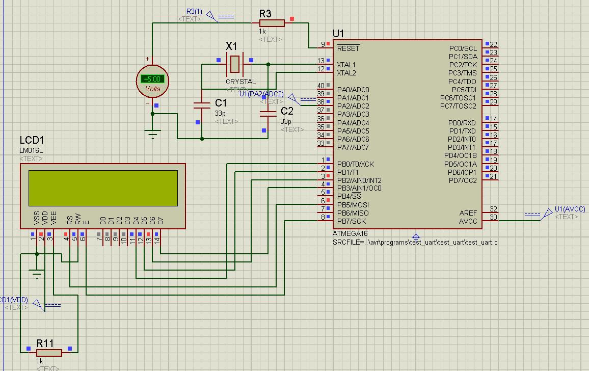
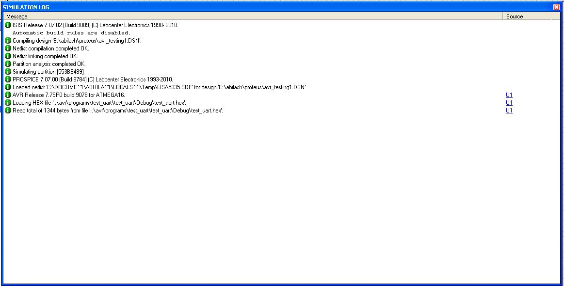
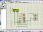
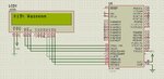
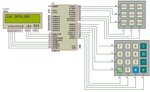
i am build a circuit in Proteus 7 professional using at-mega 16 and 16x2 LCD display. i have a code for display. the code is working with avr simulator.
but in Proteus simulation the display not working .
what is the problem? please help me, asap..

thanks...
 

hi,
i am sorry. i can't get what you say. "Please put the proteus simulation page snap shot with error......."
please tell me in detail about that......
thanks....
 

Check that you have defined the correct pins port bits for the data/control connections.

If you are using 4bit mode the connection looks like
lcd.png

hi,
i am sorry. i can't get what you say. "Please put the proteus simulation page snap shot with error......."
please tell me in detail about that......
thanks....

He is just asking for the schematic of your circuit and the error shown in the log

Alex
 
D0,1,2,3 can't be left floating, you have to connect them to GND as shown in my schematic

Alex
 

hi,
the simulation log is given below.

<a href="http://obrazki.elektroda.pl/27_1312440952.jpg"><img src="http://obrazki.elektroda.pl/27_1312440952_thumb.jpg" alt="27_1312440952.jpg" /></a>
 

connect a pot of 10k to pin 3 of lcd... one end to +5V middle pin to pin 3 and other end of pot to ground.
then vary the pot value to see some box in lcd and then to see the output... and as alex told,, ground the unused LCD data pins....
 

connect a pot of 10k to pin 3 of lcd... one end to +5V middle pin to pin 3 and other end of pot to ground.
then vary the pot value to see some box in lcd and then to see the output... and as alex told,, ground the unused LCD data pins....

That is correct for a real circuit but in proteus there is no contrast, Vee is not modeled so the display shows the same contrast even if you leave Vee floating.

The main problem in the schematic is that the four data lines are not connected to GND

Alex
 

hi,
in practical 16x2 lcd we get a black boxes on the top line of lcd if it is not initialized, is that blocks appear in the Proteus simulation,
i don't get the blocks with different values of variable resistor.

thanks.
 

Have you connected the data lines D0, D1, D2, D3 to GND?
 

hi,

yes i am connected the D0,D1,D2,D3 lines to GND....
is the delay problem is effect the simulation? i am decrease the delay there is busy error, so i think the delay is ok..
then what is the problem? is anybody got this simulation correctly with Proteus?

thanks..
 

Hi,
i am loaded a program that working in a PIC16F877A, it work in a real board, but the same is not working Proteus simulation. when i am connecting the variable pin of the POT to the VEE pin of LCD, no signal is getting to that pin. i also connected VEE Pin to ground then no black boxes is getting.

the screen shoots i given below..


Hi i am Novice to the JHD162A lcd..
Issues: Symbols appearing even the correct data has been sent.
Controller: 89S52
Data line: port0 --connection with lcd is 8bit.

Plz somebody help me...

---------- Post added at 13:12 ---------- Previous post was at 12:56 ----------

Hi i am Novice to the JHD162A lcd..
Issues: Symbols appearing even the correct data has been sent.
Controller: 89S52
Data line: port0 --connection with lcd is 8bit.

Plz somebody help me...
 

connect RW pin to data pin of microcontroller (PB0-PB7).
 

Hi i am Novice to the JHD162A lcd..
Issues: Symbols appearing even the correct data has been sent.
Controller: 89S52
Data line: port0 --connection with lcd is 8bit.

Plz somebody help me...

---------- Post added at 13:12 ---------- Previous post was at 12:56 ----------

Hi i am Novice to the JHD162A lcd..
Issues: Symbols appearing even the correct data has been sent.
Controller: 89S52
Data line: port0 --connection with lcd is 8bit.

Plz somebody help me...


if you using PORT 0 as data pins then check you have connected pull ups to port 0.

- - - Updated - - -

Hi,
i am loaded a program that working in a PIC16F877A, it work in a real board, but the same is not working Proteus simulation. when i am connecting the variable pin of the POT to the VEE pin of LCD, no signal is getting to that pin. i also connected VEE Pin to ground then no black boxes is getting.

the screen shoots i given below..


see below images its working. You should change VEE pin to floating.
 

Attachments

  • pic1.PNG
    pic1.PNG
    77.8 KB · Views: 372
  • 71_1181609411.jpg
    71_1181609411.jpg
    84.6 KB · Views: 249
  • scientific-calculator.jpg
    scientific-calculator.jpg
    60.7 KB · Views: 315

Just a few points about simulating a 16x2 LCD display in Proteus, you don't need to connect the unused data lines to ground in Proteus or in the real circuit although it may be advisable to do so, nor do you need the contrast control in Proteus but it must be connected on the real circuit. The Proteus model for the 16X2 display is correct except for the scroll command which causes the LCD to scroll in the wrong direction. Also you don't get the black box's in Proteus for a uninitialized display as you do on the real circuit. I don't think that there is anything wrong with your circuit but in your software.
 

Status
Not open for further replies.

Part and Inventory Search

Welcome to EDABoard.com

Sponsor

Back
Top