Continue to Site

Welcome to EDAboard.com

Welcome to our site! EDAboard.com is an international Electronics Discussion Forum focused on EDA software, circuits, schematics, books, theory, papers, asic, pld, 8051, DSP, Network, RF, Analog Design, PCB, Service Manuals... and a whole lot more! To participate you need to register. Registration is free. Click here to register now.

What is the pupose of diode in the diagram??

Status
Not open for further replies.

angy

Full Member level 3
Joined
Jul 9, 2008
Messages
151
Helped
5
Reputation
10
Reaction score
5
Trophy points
1,298
Activity points
2,341
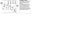
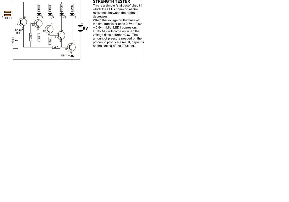
I was wondering what is the use of adding 1N4148 diode in the circuit.Cant we directly connect the emitter to ground. This kind design has been used in many circuits.


Perhaps the author likes to start from 1.8V than 1.2V.
One may think the diode is added as a protection from a possible reverse polarity since the Veb (from E to B) breakdown is usually low. In this case it is better to use a diode with a higher breakdown voltage than 100V.

On the other hand, it is better to add a resistor at the entry base as 1K or 2K2 for example.

Kerim

Edited:
Since the 4 limiting current resistors have the same value, one may notice a slight brightness differences. LED_1 has the highest brigthness, LED_4 the lowest due to the higher voltage at the collector of its transistor.
 
Last edited:

It should work with it shorted out. The only reason I can see for it is to give it an extra 0.6V start threshold. Whether this is to overcome the effects of leakage in the transistors or to linearize the steps is uncertain.

Brian.
 

What is the purpose( application) of adding diode D1 in the figure. IS it to protect from noise


---------- Post added at 10:00 ---------- Previous post was at 09:59 ----------

What is the purpose( application) of adding diode D1 in the figure. IS it to protect from noise


Here the diode is to block a possible high reverse voltage to protect the B-E junction of the npn transistor. As you see the input signal is AC. While its negative peak voltage likely doesn't exceed the breakdown voltage of the base-emitter junction, it is good to assume it may happen :)

Of course we can't be sure if it has the second function since we have no idea about the input signal (like a math problem misses some variables). So in case the signal voltage is relatively high, the amplifier will run in class C and the clipping voltage at the first transistor base will be higher (the sum of forward voltages; B-E and the diode). I think this doesn't apply here, the amplifier looks as it runs in class A (linear).
 
Last edited:

I have read a patent that tells adding diode in current branch to improve EMI.
 

Sorry iDidnt upload the circuit This query is with ref to circuit given


Now if we have a circuit anlaysis as shown D1 is used .Do we need to add this diode in circuit if yes why.

 
Last edited:

Yes, one needs to add it in the real circuit, unless he likes to redesign the amplifier since removing D1 will change the bias point of the first transistor.

Kerim

Added:
Do you know what is expected for the circuit to do?... for which sort of input signal?... for which sort of load at its ouput?
 
Last edited:

Sorry i Didnt upload the circuit This query is with ref to circuit given


Now if we have a circuit anlaysis as shown D1 is used .Do we need to add this diode in circuit if yes why.
 

The circuit operats on 1.5 volts. Biasing shows it is switching application. Diode raises Ve to 1.2 volts wile Vb is less than .5 volts. So .7 volts for noise margin is available.
Sorry i Didnt upload the circuit This query is with ref to circuit given


Student may have to more carefull while calculating current through biasing resistor 8-O with 1.2 volts on base.
 
Last edited:

Hi again,

I don't think I will use 1N1183 (rated for 35A) in such a circuit :wink:

But a diode here is good for protection since it is possible for the 27V to be applied by mistake with a reversed polarity.
The B-E junction cannot block more than about 5 volts while the diode can.

On the other hand, I don't see anything on the circuit which helps the coil current to be discharged (when the transistor is off) to avoid the temporary voltage breakdown at the transistor's collector.

Kerim
 
  • Like
Reactions: angy

    angy

    Points: 2
    Helpful Answer Positive Rating
Status
Not open for further replies.

Part and Inventory Search

Welcome to EDABoard.com

Sponsor

Back
Top