Tahmid
Advanced Member level 6
- Joined
- Jun 17, 2008
- Messages
- 4,756
- Helped
- 1,798
- Reputation
- 3,588
- Reaction score
- 1,656
- Trophy points
- 1,413
- Location
- Berkeley, California
- Activity points
- 30,584
ahehehe.. very nice discussion guys... dont worry I will try both circuits and let you know..")
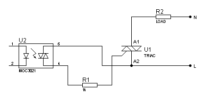
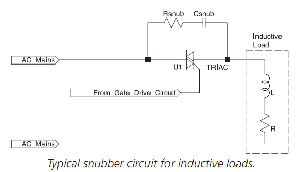
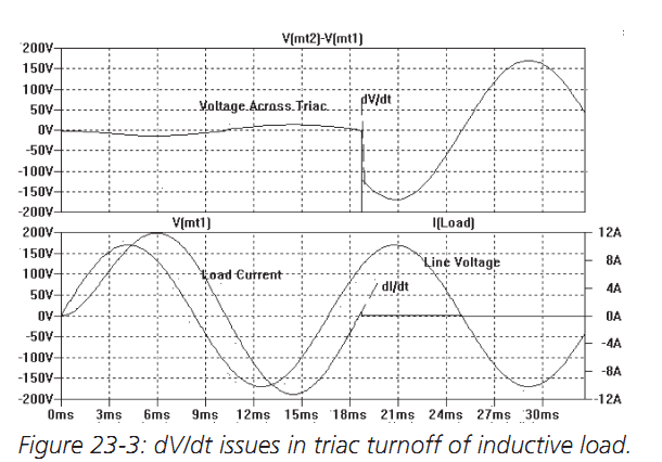
Your load is a lamp, right? When using inductive loads, make sure you use a snubber. For resistive loads, a snubber is not required.