Continue to Site

Welcome to EDAboard.com

Welcome to our site! EDAboard.com is an international Electronics Discussion Forum focused on EDA software, circuits, schematics, books, theory, papers, asic, pld, 8051, DSP, Network, RF, Analog Design, PCB, Service Manuals... and a whole lot more! To participate you need to register. Registration is free. Click here to register now.

workings of center tapped transformer

Status
Not open for further replies.

PG1995

Full Member level 5
Joined
Apr 18, 2011
Messages
248
Helped
1
Reputation
2
Reaction score
1
Trophy points
1,298
Activity points
3,758
Hi

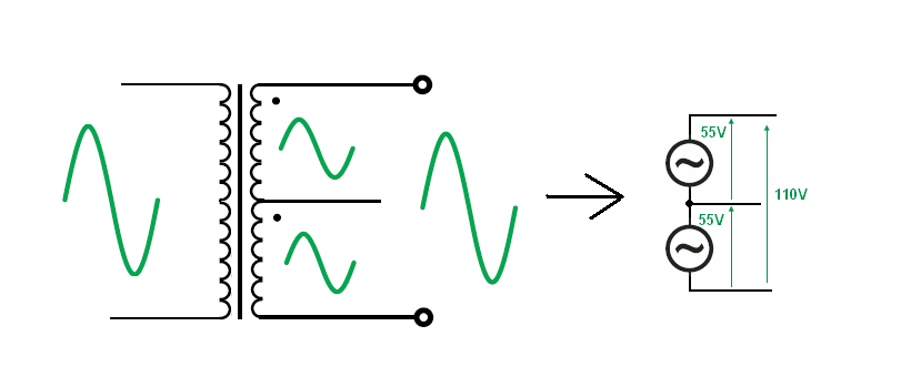
I'm trying to understand how a center-tapped transformer or CTT. Please help me to understand how it works.

I have some basic understanding of how a simple transformer works. I have tried to let you know what is hampering my understanding by drawing a diagram and asking some of my questions there on the diagram. Please have a look on the linked diagram:
https://img163.imageshack.us/img163/538/imgvgg.jpg
 

It will be from A to G.

The voltage induced is going to depend on the turns ratio. So 110 or 55 entirely depends on the number of turns in secondary to primary
 
  • Like
Reactions: PG1995

    PG1995

    Points: 2
    Helpful Answer Positive Rating
When there are many coils coupled to each other (having the same iron core for example), we may add a dot at one terminal of each of them to define their polarity. When one terminal with a dot is known to be positive, all other terminals will have the same polarity hence positive. In your example there are three coils. So if there will be a further analysis you may like to add 3 dots to CTT :wink:

CTT allows us to use just 2 diodes. And you are right, each of the two secondary coils delivers half the load power, that is half its current. That is why the section of the copper wire of these coils could be made smaller since it will carry just half cycles of the current.

Obviously one can ignore the tap terminal and use the two coils as one to get twice the voltage. The rectifier part would consist of 4 diodes (called 4-diode bridge).

Also we can keep the tap terminal as a reference (ground) and add another 2-diode rectifier (but in reverse) to give a minus output relative to ground. In this case we get +/- 55V in your example, hence a total difference 110V.

Kerim
 
  • Like
Reactions: PG1995

    PG1995

    Points: 2
    Helpful Answer Positive Rating
We can look at secondary voltage as a series connection of two AC voltage source
 
  • Like
Reactions: PG1995

    PG1995

    Points: 2
    Helpful Answer Positive Rating
When there are many coils coupled to each other (having the same iron core for example), we may add a dot at one terminal of each of them to define their polarity. When one terminal with a dot is known to be positive, all other terminals will have the same polarity hence positive. In your example there are three coils. So if there will be a further analysis you may like to add 3 dots to CTT :wink:

Thank you, Kerim.

In this diagram Jony has also used two dots above the secondary coils. What do they stand for? Does that mean both secondaries carry the current in the same direction? Please help me understand this. Thanks.
 

This dots indicate the polarity of a voltages.
Read once again what KerimF wrote
When there are many coils coupled to each other (having the same iron core for example), we may add a dot at one terminal of each of them to define their polarity. When one terminal with a dot is known to be positive, all other terminals will have the same polarity hence positive.
Dot convention - Wikipedia, the free encyclopedia
 

Please remember that each coil has 2 terminals.
So if one terminal has a dot, the other one won't have.
In CTT, the secondary has 2 coils hence when the transformer is under construction we have 4 terminals at the secondary side first.

Usually we wind these 2 coils simultanuously (2 wires in parallel for example).
So at one end, we have A1 (for coil 1) and A2 (for coil 2).
Obviously at the other end, there will be B1 (coil 1) and B2 (coil 2).
In other words, A1-B1 (wire of coil 1) and A2-B2 (wire of coil 2).

So if A1 has a dot, A2 should have a dot too (B1 and B2 won't have a dot).
This means if Va1 > Vb1 (for coil 1), Va2 > Vb2 (coil 2).
Note please that if we decide to join A1 and A2 also B1 and B2, we would get just one secondary coil formed by 2 wires.

Now it is time to get the 3 terminals at the CTT secondary side:

A1 will become your terminal A (on your pic)
B1 + A2 will be your terminal B
B2 will be your C.

We say here that we connect the two coils (wind in parallel to let them have the same magnetic flux) in series hence from A1 to B2 the voltage is doubled; (Va1-Vb1) + (Va2-Vb2).

On the pic of jony130, there are 2 dots which are in our example denote the terminals A1 (of coil 1) and A2 (of coil 2).
So on your pic if Va > Vb, Vb > Vc. Please note that the dots are about voltages not currents.
I am saying this because if we add a 3rd dot at your terminal E (primary side), when Ve > Vf, it likely means that a current enters the coil from e to f. But at the secondary since Va > Vb a current should go out from A to the load, so the current direction is from B to A inside the coil. So please remember that "dots are better seen as defining the polarity of coil terminal voltages, not the coil current directions".

Kerim

Edited:
Many mistypes are corrected above concerning coil terminal lables... sorry for any inconvenience.
 
Last edited:
  • Like
Reactions: PG1995

    PG1995

    Points: 2
    Helpful Answer Positive Rating
Status
Not open for further replies.

Part and Inventory Search

Welcome to EDABoard.com

Sponsor

Back
Top