dayanpad
Advanced Member level 4
Dear all
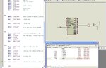
following codes using assembly for CCP capture mode (MPLAB IDE)
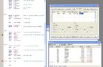
after compile, I loaded hex file in to PIC simulator IDE
then i pressed several time RC2 pin
as per my program TMR1L and TMR1H should be capture to CCPR1L and CCPR1H
but it does not happened
let me know the reason
MCU 16F877A
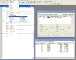
following codes using assembly for CCP capture mode (MPLAB IDE)
after compile, I loaded hex file in to PIC simulator IDE
then i pressed several time RC2 pin
as per my program TMR1L and TMR1H should be capture to CCPR1L and CCPR1H
but it does not happened
let me know the reason
MCU 16F877A
HTML:
movlw 	b'00000101'
			movwf 	ccp1con    		 ;start with rising CAPTURE
			bcf		pir1,2
			movlw 	b'00000001'
			movwf 	t1con          ; on timer
Wait
			btfss 	pir1,2
			goto 	Wait
Last edited: