Continue to Site

Welcome to EDAboard.com

Welcome to our site! EDAboard.com is an international Electronics Discussion Forum focused on EDA software, circuits, schematics, books, theory, papers, asic, pld, 8051, DSP, Network, RF, Analog Design, PCB, Service Manuals... and a whole lot more! To participate you need to register. Registration is free. Click here to register now.

Triangular wave generator

Status
Not open for further replies.

themaccabee

Full Member level 4
Joined
Apr 1, 2007
Messages
201
Helped
6
Reputation
12
Reaction score
6
Trophy points
1,298
Activity points
3,003
Hi,

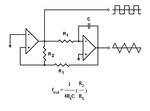
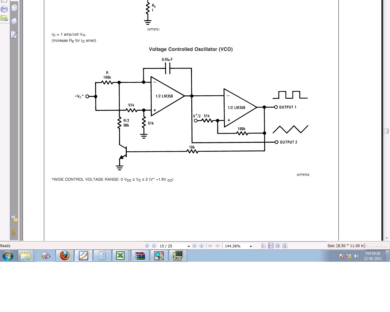
I need to generate a 10kHz triangular wave 0 to 5V level..
I ve the facility to generate a sqaure wave of desired frequency 0 to 5V level. I just need to convert it to trangular wave form.I ve 555 timer, some opamps if needed. Very tight linearity is not required.Its for testing purpposes..What can be a simple solution?
 

You may use a separate integrator to generate a ramp voltage from the generated square wave.
The triangle wave's amplitude is set by the ratio of R1/R2.

f OUT = (1/4RtC) (R2/R1)
 

Attachments

  • square_triangle_gen.gif
    square_triangle_gen.gif
    3.7 KB · Views: 216

Do you need "roughly", or "exactly" 10kHz?

In ICs I prefer a switched current source and capacitor for timing ramps.
Actually a pair, 1X source + switched 2X sink. Pair of comparators at
3/4*vdd and 1/4*vdd. When ramp gets to top, set FF enabling the sink
current; when ramp gets to bottom, reset. An A=2, ref=vdd/2 op amp
will turn that to a full swing (subject to amp capabilities, amp can be
powered off wider rails) 0-5 t-wave.
 

Hi,

with emphasis I can recommend the circuit as proposed in #2 by mister_rf.
It is simple and reliable. It is a derivat of the well known Schmitt trigger oscillator (astable multivibrator).
 

Thank you all for the suggestions,
I'm thinking of 2 op-amp circuit. By the way in the NE566 solution , if Im operating on single ended supply the output is typically 2.4Vpp. Is that referenced to ground that is 0-2.4V or if itsnt how to convert it to 0-5V scale?
Regards,
 

Do you have rail to rail opamp? If you do, then the circuit of post #2 will be a good choice by adding a virtual ground at 2.5V.

Added:
For instance, the difficulty of your problem is that your supply is 0-5V and you look to have a triangular wave also between 0-5V. At the two peaks, there will be always a small non-linear region.
 
Last edited:

Okie i was checking the LM358 dual opamp to build this circuitry , i looked into the datasheet and saw a transistor connected in the VCO circuit.
Can some body tell me what is the exact purpose of the transistor??
 

It is used to discharge the capacitor.
 

since the opamp inverting input is a constant voltage the feedback capacitor requirers a constant current dishrge......
this is achieved using the transistor.Capacitor disharges till the next threshold/reference value.
 

Status
Not open for further replies.

Similar threads

Part and Inventory Search

Welcome to EDABoard.com

Sponsor

Back
Top