Continue to Site

Welcome to EDAboard.com

Welcome to our site! EDAboard.com is an international Electronics Discussion Forum focused on EDA software, circuits, schematics, books, theory, papers, asic, pld, 8051, DSP, Network, RF, Analog Design, PCB, Service Manuals... and a whole lot more! To participate you need to register. Registration is free. Click here to register now.

"backategate coupling" In the chapter 6, of (Jan M. Rabaey)

Status
Not open for further replies.

palmeiras

Full Member level 6
Joined
Feb 22, 2010
Messages
375
Helped
61
Reputation
122
Reaction score
50
Trophy points
1,308
Location
South America
Activity points
4,199
Hi everyone,

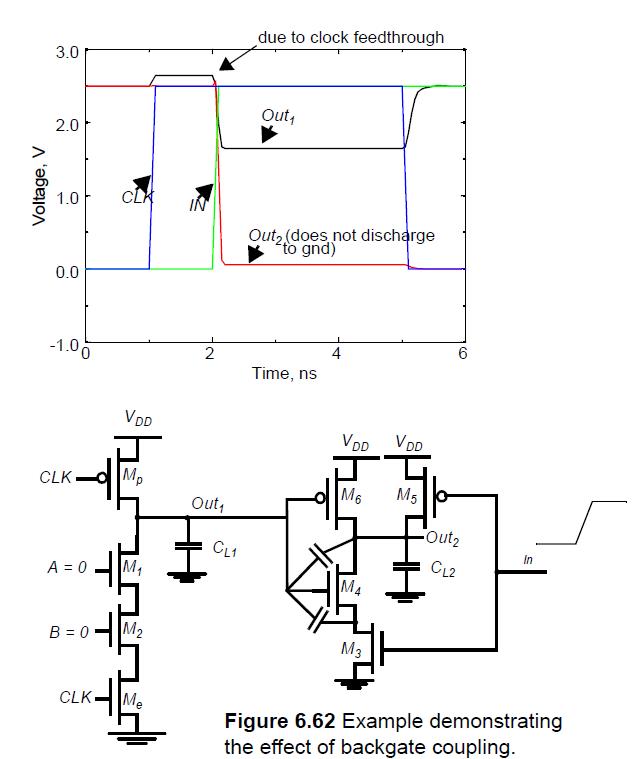
In the chapter 6, of (Jan M. Rabaey), he explains the “backategate coupling”.
This effect is shown in the attached figure.
Please, could someone explain why Cout2 does not go to exact gnd – when “in” goes from zero to 1? The figure shows that it Is not possible to completely discharge capacitor CL2.

Thank you,

Regards,


The circuit you have drawn is dynamic logic circuit. So the principle behind the capacitive coupling is that the voltage at CL1 starts charging CL2 even though CL2 discharges through M3 and M4. Thus, Out1 voltage drops charging Out2 which is not able to discharge to GND.
 

kalyanasv,

Thanks for your reply.
I didn’t understand you explanation, because the circuit in this situation has a direct path to ground. The terminals of any parasitic capacitance connected in this path will be set to gnd.
So again, why cout2 does not achieve gnd?

Thanks,
 

Here out2 gets charged by out1 [capacitor connection between M4 Gate-drain]. Thereby though CL2 at out2 would discharge it won't be able to completely.
 

Status
Not open for further replies.

Part and Inventory Search

Welcome to EDABoard.com

Sponsor

Back
Top