Continue to Site
Follow along with the video below to see how to install our site as a web app on your home screen.
Note: This feature may not be available in some browsers.
i m doing a project on solar tracking system using mppt and using pic16F877A.we had doubt that how many LDR (light dependent resistor)are supposed to be used and where it has to be placed according to intensity of sun light please give some ideas.
Hi ,i think it should be 4 LDRs 2 each in elevation and azimuth
control should operate the motor or whatever mechanism is, so as both thr LDR in one direction heve equal intensity
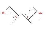
LDR have to be covered in short black tubes and need to have a delay to allow for passing clouds
regards
Hi sreeja,i m doing a project on solar tracking system using mppt and using pic16F877A.we had doubt that how many LDR (light dependent resistor)are supposed to be used and where it has to be placed according to intensity of sun light please give some ideas.
It sounds like it's simply too bright for the LDR and you are off it's 'linear' brightness/resistance curve.
Your options are:
1. reduce the series resistors but this will increase current consumption and heating in the LDR which will make the reading less reliable.
2. shade the LDRs to prevent as much light falling on them. A trick I've used with outdoor webcams is to place a 'reactolite' photochromic lens from sunglasses over the camera lens to increase the range of light it can cope with.
3. possibly use a different method of detecting the light direction: place four LDRs as close together as possible in a square arrangement and cover them at a distance of a few cm away with a black shield. In the shield put one small hole directly over the center of the square. Now as the light angle changes the beam of light falling through the hole will fall unevenly on the LDRs to allow you to determine the movement needed to centralize it. The advantage of this method is you can adjust the hole size to cater for different light levels.
Brian.
I am doing the same project..
I got some problem: The LDR under shade and the LDR under direct sunlight has the same reading.. The resistant of both LDRs are very low when I test them outside.
Currently it only work when demo with a flash light indoors.
- - - Updated - - -
PS: The resistor I used as Voltage divider is 47k ohm.
")