Continue to Site

Welcome to EDAboard.com

Welcome to our site! EDAboard.com is an international Electronics Discussion Forum focused on EDA software, circuits, schematics, books, theory, papers, asic, pld, 8051, DSP, Network, RF, Analog Design, PCB, Service Manuals... and a whole lot more! To participate you need to register. Registration is free. Click here to register now.

[SOLVED] reading schematics issue

Status
Not open for further replies.

this

Member level 2
Joined
Apr 14, 2011
Messages
44
Helped
4
Reputation
8
Reaction score
4
Trophy points
1,288
Activity points
1,623
Hi
I know it's probably very simple question, but I wasn't sure how to ask google :)
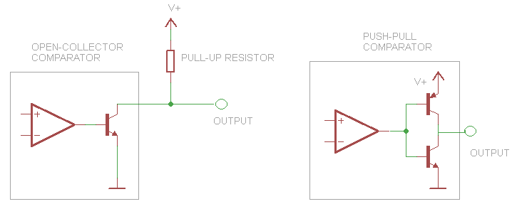
So, I got this schematic:
**broken link removed**
and I'm not sure what do I do with the part in left-bottom corner as it's separated from the rest of the circuit.

TIA
 
Last edited by a moderator:

the left part of the circuit shows the power supply connection.
The +9v in left part is to be connected to all the points where it is marked as +9v.

and the gnd symbol, is to connected to all points where it is shown in the schematic.

it is a convenient way of drawing power supply.
so that you need not show the individual connection to supply by wire line.

in general , the rule is connect all points that have the same node symbols.

hope it is clear.
 
  • Like
Reactions: this

    this

    Points: 2
    Helpful Answer Positive Rating
That is the +9V supply for the circuit. Just connect the +9V output from the battery switch to the three points that are labeled +9V. Supplies are often drawn like that to avoid a lot of confusing lines. Similarly, wires connecting all of the grounds are not shown for clarity.

This schematic also doesn't show a "decoupling" capacitor across the power pins (4,8 ) of the TLV3702. I suspect there is one (0.1 uF ceramic) attached very close to the pins. There have been extensive discussions here on decoupling capacitors.

Here is a link to that thread: https://www.edaboard.com/threads/212775/

John
 

Thanks for your answers guys.
From what I understand it should be something like this:(sorry for really bad drawing:) )
**broken link removed**
And all ground connections should just go to negative battery terminal. Is this correct?

Thanks for your patience :)
 

No! You have the battery connected backward. The triangle is "Ground." The plus side of the battery has the switch. That goes to th +9V symbols.

The battery symbol is the thing with the long line/short line/long line/short line,etc. The short line is ground ("-"). You do not need another battery.

Sorry, I misunderstood your original question. That "thing" is the battery.

John
 
  • Like
Reactions: this

    this

    Points: 2
    Helpful Answer Positive Rating
All the triangles represent the ground and should be connected between them.
All the +9 symbols are the positive supply and should be connected between them

81860888.gif

Alex
 
  • Like
Reactions: this

    this

    Points: 2
    Helpful Answer Positive Rating
I know it's a battery symbol, sorry, I mixed it all up, brain fart.
Disregard my drawing please, let's start again.

"Supply circuit" - the separated part of the original drawing(the one I moved to the right-top corrner and added some rubbish)
"Main circuit" - rest of the original drawing.

1)All "+9" parts of the main circuit should be connected to "+9" lead of supply circuit.
2)All gnd parts of main circuit goes to negative battery terminal.
Is this correct now?

--edit
OK, thank you all, got this now. I knew it was simple :)
 

this,

the same way you can adopt GND symbol ( wich implicitly connects all them ), also can represents VCC separatelly ( here, denoted by +9v ), in order to clarify design.

+++
 

I don't know if I should create new thread for this, so I'll ask here:
I don't have TLV3702 but I have LM393N, may I use it as a replacement?
Quick googleing suggest that I could, but I want just want to be sure.
 

I don't think so. The LM393 is open collector output. The TLV3702 is push-pull output -- it can actually source current. I need to try to find the block schematic for the TLV3702 to confirm that. If you look at your circuit, effectively grounding pin 7 (open collector) in the top comparator won' do much.

Unfortunately, I am at dinner time, so I need to take a break for an hour or so. That probably won't work well for your time zone. I will look at it later. Maybe someone else will have a definitive answer before then. Your circuit might be modified to work with the LM393, though. A simple pull-up resistor on each out put may work.

John
 

Here is a comparison of the two types of comparator outputs:


Everything inside the gray rectangles is inside the comparator. The push-pull type has an internal connection to V+. It can source or sink current. The open-collector (also called, open-drain) type can only sink current to ground when the output transistor is turned on. An external resistor ("pull-up" resistor), makes the output voltage high when the output transistor is off. Current is sourced through that resistor. For more detail see: Comparator - Wikipedia, the free encyclopedia. Scroll to Output type.

Can your LM393 replace the TVL3702? I don't know for sure, but you can give it a try. The circuit does not appear to be too demanding on the comparators, except they need to source current. So, you could try a pull-up resistor on each output.

What size resistor? For the greatest voltage swing, you would use a large resistor, such as 10K; however, that won't be able to provide much current. On the other hand, a much smaller resistor will use quite a bit of current when the output transistor turns on, because it will be connected directly from V+ to ground minus the voltage drop of that output transistor. You want both good current and a large voltage swing to turn on the 2N7000 mosfet. I would try a 1K resistor (the LM393 is limited to 18 mA current sink on its output). If that doesn't turn on the mosfet, then I would try 4.7K or whatever resistor you have that is larger.

Please give us updates. There are numerous push-pull comparators made. You may be able to get one of them instead of the TLV3702, if these modifications do not work.

John
 
Last edited by a moderator:

Status
Not open for further replies.

Similar threads

Part and Inventory Search

Welcome to EDABoard.com

Sponsor

Back
Top