Continue to Site

Welcome to EDAboard.com

Welcome to our site! EDAboard.com is an international Electronics Discussion Forum focused on EDA software, circuits, schematics, books, theory, papers, asic, pld, 8051, DSP, Network, RF, Analog Design, PCB, Service Manuals... and a whole lot more! To participate you need to register. Registration is free. Click here to register now.

Boost Converter Average current control mode, doubt regarding reference current.

Status
Not open for further replies.

AbhimanyuSingh

Member level 1
Joined
Jul 7, 2010
Messages
36
Helped
0
Reputation
0
Reaction score
0
Trophy points
1,286
Location
chennai
Activity points
1,563
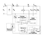
How does one obtain the reference current by measuring the output voltage of the Boost PFC converter. I assume that the load is unknown, ie changes with time. Or am I wrong? Why do I need to measure the output voltage to find reference current. Every book I have come across tells the procedure to find out the reference current. But no one explains the idea behind it. Or else there is something I am missing. But I havent understood how to calculate the constants and values to be multiplies with the measured output voltage to calculate the reference current. can someone help me with this? Or sugggest me a book or literature which can clarify this? Thanks in advance.
 

Not knowing the topology you're using...

Some voltage or current regulators sense a current through a resistor inline with a load. The load can be any value.

The resistor is chosen to produce a certain voltage across it. The sense wire is connected between the resistor and your load.

It stands to reason that your converter needs to sense the output voltage moment to moment. Or output current depending on what method its regulation operates on.
 

What exactly do you mean by reference current? Do you mean one of the inputs to the current error amplifier? The output of the multiplier?

I don't think it's possible to tell the input/output current from the average output voltage. However, you should be able to tell roughly what the input current is based on the AC component of the output voltage.
 
All I can give is one or two concepts of operation that I've picked up, not having worked with a boost PFC converter.

At times like this it's hard for anyone to reply further unless you post a schematic.
Or post a link to the circuit you're using.
Or to state what device you're using, or its datasheet, etc.
 
Thanks mtwieg for the concern.
by reference current i mean the input of the current error amplifier.

I am uploading an image if a typical boost ACMC circuit.
 

Attachments

  • dfsdfsd.JPG
    dfsdfsd.JPG
    31.7 KB · Views: 91

Looking at the schematic...

Yes. R_S appears to be how you get a reference current. It's attached to the input of the current error amplifier.

R_S operates by taking a portion of the AC output coming from the current error amplifier, and diverts it to ground.

You could say it alters voltage at the amplifier input. However its purpose is different and distinct from the voltage reference at bottom right of the schematic. Hence they call the pin a current sense pin, not a voltage reference pin.

Presumably you'll need to experiment with R_S value in order to get the current output you want. Or maybe it's for current limiting instead?
 

What I want to know is how do we know the multiplication constant before the multiplier to get the output of the multiplier, which goes in the non inverting input of error amplifier. I can even somehow go for trial and error 100s of times to find the value of the multiplier constant, but what I want to know is, what is the relation between the reference current (output of multiplier) and the output voltage? Why one goes for measuring the output voltage and then comapring it with a reference voltage and then multiplying it with the input sinusoidal voltage. Why does all these lead to reference current, which is the non-inverting input of the current error amplifier. I am yet not sure whether I am clear or confusing. Apologies.
 

I fear, your question doesn't become much clearer with the block diagram. Reference current refers to the quantity z, output of the multiplier, I guess. But wha do you mean with "does one obtain the reference current"? Are you asking for the PFC operation principle or a particular measurement you want to perform? If the latter, which information you are looking for? In steady state, the output voltage will be equal to the setpoint and doesn't hold a particular information. The load curent would be more interesting and allow some simple calculation based on conservation of energy.

You may want to give an example of the said procedures found in "every book" to make us understand what you are actually looking for.

P.S.: Reviewing your last post, I understood that you are asking for the operation principle of the PFC control circuit. I hope, you understood it's purpose, forcing the current waveform drawn from the mains to a sine.

The output of the voltage error amplifier can be simply seen as a slowly variable quantity that tracks the power demand of the load automatically. The error amplifier has typically a PI characteristic. It's integrator action results in zero error in steady state.

A constant in front of the multiplier won't change anything, except for the control loop gain and still result in the same reference current. This is because the error amplifier will change it's output voltage until the necessary reference current is achieved. Loop gain is important to setup a stable controller, but the exact quantity can be ignored, when you try to understand the operation principle.

P.S.: I think, it's helpful to think about the conservation of energy aspect. For a particular output power, a specific input current magnitude is required. The control loop achieves this by varying the reference current.
 
Last edited:
Yes, I mean the principle of operation of PFC. All i know is that the inductor current and the load current in a boost converter are related by: I_L * (1-D) = I_load. Here, they measure the output voltage use it to get the reference for inductor current for high power factor. The load voltage is a simple DC with ripples. How is it related to the desired inductor current? As far as the example is concerned, every book tells the procedure about measuring the output voltage, then comparing it with a reference voltage, using some compensator, then multiplying it with a constant and the the sinusoidal input voltage. Doing all this gives the reference current for current error amplifier.
 

What I want to know is how do we know the multiplication constant before the multiplier to get the output of the multiplier, which goes in the non inverting input of error amplifier. I can even somehow go for trial and error 100s of times to find the value of the multiplier constant, but what I want to know is, what is the relation between the reference current (output of multiplier) and the output voltage? Why one goes for measuring the output voltage and then comapring it with a reference voltage and then multiplying it with the input sinusoidal voltage. Why does all these lead to reference current, which is the non-inverting input of the current error amplifier. I am yet not sure whether I am clear or confusing. Apologies.
Okay, so your question is about the operating principal of a PFC, rather than how to do some specific measurement. That makes it easier.

The reason the output of the voltage error amplifier (the one comparing the output voltage to a reference voltage) is multiplied by the instantaneous input voltage is because the instantaneous input current needs to be proportional to both. You know the basic operating principle of a simple current mode controller (with no PFC), right? The output of the voltage error amplifier directly controls the input current, either with a comparator (making a simple peak current mode controller) or a error amplifier (making an average current mode controller). In a PFC, the same thing is being done; the output of the voltage error amplifier determines the amount of input current demanded from the source. However in a PFC, a multiplier is stuck in between, and the input voltage is connected to its other input. This is done so that the shape of the current is forced into the same shape as the input voltage, which is how PFC is realized. However, the amplitude of that current reference waveform is still controlled by the voltage error amplifier, and thus there's no real change in the system transfer function. It's still a (average) current mode supply.

Of course determining the gain of the multiplier has to be done correctly too. Were you also asking how to measure that?
 

Thanks FvM, thanks mtwieg. Your explanations are what I needed. Yes, method to determine the gain of the multiplier will be very helpful too.
 

To clarify, do you want to determine what the gain of an existing design is, or decide on a gain for a design you're doing yourself?
 

I want to decide the gain of a design I am doing for myself. What should be the approach other than hit and trial.
 

Status
Not open for further replies.

Part and Inventory Search

Welcome to EDABoard.com

Sponsor

Back
Top