Continue to Site

Welcome to EDAboard.com

Welcome to our site! EDAboard.com is an international Electronics Discussion Forum focused on EDA software, circuits, schematics, books, theory, papers, asic, pld, 8051, DSP, Network, RF, Analog Design, PCB, Service Manuals... and a whole lot more! To participate you need to register. Registration is free. Click here to register now.

Ferrite loopstick antenna

Status
Not open for further replies.
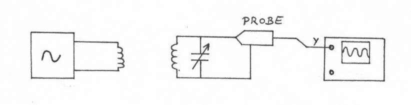
What is inductance value and frequency? Unload Q looks a bit low but until I know inductance and freq won't know for sure. Also show exactly how you coupled into tank to make unloaded Q measurement.
 

L = 105 hH, C = 51.6 pF, measured with a LC meter.

To make the Q measurement I've done as you've said some time ago:
**broken link removed**

Ah, maybe the 50 ohm input of the spectrum analyzer could be a problem?

Thanks
 

Assuming both the generator and spectrum analyser are 50 ohms you are projecting 317K || 10 pF from each end (at 4 MHz) so you are loading tank with 158k and 20 pF. The 158K should be high enough compared to Rp of coil.

So you have 20pF + 51.6 pF = 71.6 pF parallel resonanting with 105 uH. Resonant freq should be 1.84 MHz not 4 MHz. So you either have wrong assumption on 51.6 pF or 105 uH if you are seeing resonance at 4 MHz.

The best way is to put a fixed known capacitor in parallel with coil. Change out fixed known capacitors until you get resonance close to 4 MHz.

Assuming your 51.6 pF and two 10 pF caps are correct, then you really have a 22.1 uH coil for it to resonate at 4 MHz. If you measured 23 kHz 3db BW at 4 MHz then the Q is 4 MHz / 23 kHz = 173.9 and parallel Rp is 555.7 x 173.9 = 96.6 kohms. Does not pass sanity check. At that Rp the 158k test load matters and true coil Rp would be like 250k. Not believeable.
 
Last edited:

sorry! my mistake.. I've forgotten to say that I've done these tests with 2 MHz resonance..sorry..

Maybe 1/2*π*√LC isn't exactly 2 MHz in theory, but in practice is the value that corresponds to the maximum amplitude of the 2 MHz harmonic.

Another thing, the generator has high impedance output..

Thanks again for your willingness..

What exactly does high impedance output mean? Capacitance now matters, cable capacitance now matters.
 

Instruments usually have 50 ohm or high impedance output/input.. My generator has high Z output. I don't know the exact value (also oscilloscope has high Z input but i've never known the value...)
Apart from cable capacitance ( hard to measure exactly), the values that I've measured are reasonable for 2 MHz? And my calculation are the correct way to match the LC impedance?

I'm asking because I need to understand if i'm doing everything wrong or not..

Thanks
 

Also, I really don't understand where does come from some numbers in your calculations in post #23:
Assuming both the generator and spectrum analyser are 50 ohms you are projecting 317K || 10 pF from each end (at 4 MHz) so you are loading tank with 158k and 20 pF.
Ok, assuming instruments are 50 ohm. What's 317K?

I'm re-doing all calculations, please tell me if I'm right.
Assuming that my starting point is this one:
**broken link removed**

Rp = Q √LC ≈ 10K.

Now the goal should be finding the value of a matching capacitor that eliminates the complex part of the total impedance. Right?
So: ZL and ZC at the resonance (2 MHz) have the same value = 1320j.

Z1 = ZL // ZC = 660j.
ZTOT = Z1 // RP = 43 + 657j.

So I've to insert, in series with LC, a cap with value -657j = 121 pF.
In this way remains only a real impedance of 43 ohm.

Now the final situation should be this:
**broken link removed**

I hope I'm doing everything in the right way...

Thanks
 

please tell me if I'm right or wrong..
 

Hi,

I'm re-reading this thread to understand better the problem that I'm facing.

@RCinFLA: about this post:
On a wild guess, the parallel Rp of the ferrite tank will be in the range of 5k to 15k ohms. If you want to drive it with a ten ohm source then configure a matching circuit to take 10 ohms to 5k ohms.

If your ferrite coil is 22 uH @ 4 MHz then you have +j553 ohms in parallel with about 5k ohms. The series equivalent is 60.5 + j546 ohms. If you add -j546 capacitor (72.8 pF cap) you would have 60.5 ohms real impedance at 4 MHz. The loaded Q will be 2500/553 = 4.5 or BW3db of 885 kHz at 4 MHz. The 2500 number assume 5k due to coil Rp and 5k in parallel due to matching loading.

I suggest you reserve some of the loading capacitance for tuning. Reserve about 10 pF for a parallel tuning cap, leaving 62 pF for matching. Change the 10 ohm to 56 ohms and connect a 62 pF in parallel with 15 pF trimmer then in series to coil. Adjust trimer to get 4 Mhz resonance.

Why, in your calculations, you don't consider the variable capacitor? Shouldn't I consider it in the calculation of the impedance? L and C in parallel, and also Rp in parallel.. Right?

However, I've measured the Q with the method described here Measuring the Q of LC circuits and I've obtained interesting results:
the ferrite sticks that I have are useless at 4 MHz, because of a Q unloaded of about 40. They works better in the 500 KHZ - 2 MHz bandwidth, so I'll use one frequency in this range.
Q @ 2 MHz = 90.
Q @ 1 MHz = 90.

But doing the calculations:
L=71.7 uH
C=83 pF;
Q = 90;
Rp is huge!! about 83 Kohm!! Is this possible?

Please tell me what you think about this considerations..
Thank you very much
 

In none of your previously presented circuits is the resonance Q determined by Rp, they are either shorted by a source impedance (post #27, first schematic), heavily loaded (post #14, post #27, second schematic). So as a first question, which circuit are you referring to with your Rp calculations?
 

Infact I've never said that I've determined Q by Rp, quite the reverse! I've measured Q, and then determined Rp with formulas.
I've measured Q with the method showed in the link that I've posted.

Post #27 was only to show my reasonings, that I don't know yet if they are correct.
Actually I have only the opamp, and the LC antenna, and I have to match their impedance...
 

O.K., you are talking about unloaded Q, not the loaded circuits discussed in this thread. When you measured Q=40 at 4 MHz, I have two questions:
- Are you sure, that the measurement is correct? What has been the voltage probe impedance?
- Why do you think that Q = 40 is useless?
 

RCinFLA talked about the unloaded Q, in post 9 and 12, so I've done some measurements..

- I think that the measurement is correct because I've used the method suggested by RCinFLA (whitch is less accurate because of the cable capacitance) and also the method suggested in the link, and the results are almost the same.
- I think that Q = 40 (unloaded) will become a very little Q when loaded... Moreover, in my application I receive several frequencies, so the selective behavior is very important...

Apart from the Q considerations, what do you think about the high value of Rp?

Thanks
 

Q values of 90 as well as the high Rp values are reasonable in my opinion.

If the circuit Q is reduced due to the load, the unloaded Q value doesn't matter much. If you refer e.g. to a parallel circuit, the lower RL will effectively determine the overall Q, Rp becomes meaningless. If you use more complex circuits like the Rmatch/Cmatch cicruit in post #27, the effect is basically the same, although some transformation applies between Rmatch and Rp, Rmatch still determines Q.
 

The correct formula for Rp is Rp = Q √LC . Isn't it?

In this case Rp accounts for the various dissipative and parasitic effects..
So, what's the RL you're talking about?

And, my main doubt: my considerations in post #27 are correct or I'm missing something?

Thanks
 

And, my main doubt: my considerations in post #27 are correct or I'm missing something?
I must confess, I even don't understand the purpose of the calculations.
Now the goal should be finding the value of a matching capacitor that eliminates the complex part of the total impedance.
The impedance of the unloaded LC circuit in resonance is real, it equals Rp. So which complex part you want to match?

For sufficient magnetic field strength, a high voltage must be applied across the LC circuit, e.g. several 10 V. According to the calculated real impedance, you don't need much power, but the generator voltage must be stepped up. You can achieve this either by connecting L and C in a series resonant circuit, or by feeding the generator output to a tapped L.
 

The correct formula for Rp is Rp = Q √LC . Isn't it?

In this case Rp accounts for the various dissipative and parasitic effects..
So, what's the RL you're talking about?

And, my main doubt: my considerations in post #27 are correct or I'm missing something?

Thanks

At resonance, Xind equals Xc. Q = Rp/Xc. For Rs, Q = Xc/Rs

For the Q testing you cannot use a HiZ source since there could be a significant amount of capacitance in the cable and output source that would screw up the resonance Xc assumption. If you can still get enough output to measure, terminate or pad down the generator to a low Z of around 50 ohms. Put a 1k resistor to generator output and 56 ohm to ground as a voltage divider that will give you a low impedance drive. Then put the series caps that lightly load the tank circuit.

Get used to converting series Rs+ jXs to parallel Rp || jXp. If your calculator has Polar to Rectangular conversion and Rect to Polar it is very easy.

Parallel notation is 1/(Rs+jXs) then invert each conductance and susceptance components. Easiest way to invert a complex number is to convert to polar form. Invert the magnitude and change sign of angle. You can then convert back to rectangular coord. and invert each part to get Rp and Xp.

For example, at 4 MHz with a 50 ohm source feeding a 10 pF series capacitor.

Xc @ 4 MHz = -j3978.9 ohms, so one side loading is 50 - j3978.9 ohms.
To convert to parallel equivalent load, 50-j3978.9 = 3979.2 /_ -89.28 degs. 1/(3979.2/_ -89.28 degs) = 0.000251 /_ +89.28 degs.
Convert back to rectangular form = 3.157 E-6 +j51 E-6 mhos. Invert real part to get Rp = 316.7k ohms. Invert imaginary to get Xcp, = -j3979.5 ohms. -j3979.5 ohms @ 4 MHz = 9.998 pF.

So Rp = 316.7 kohms (very high) and Cp = 9.998 pF. (50 ohms in series with 10 pF = 316.7k ohms || 9.998 pF, at 4 MHz)

If you have the same network for source and pickup sense then the two are in parallel so net test circuit loading is 158.3kohms || 19.997 pF. Add 19.997 pF to your parallel capacitance that is resonating coil.

Don't use a variable cap. Fixed caps are your best known reference point. Inductors stated inductance is poor since inductance of a coil can vary alot, not only due to make tolerance but also the inductance is typically highly a function of frequency. A capacitor value is less a function of frequency until you get to much higher frequency then you are dealing with.
 
Last edited:
  • Like
Reactions: vaka85

    vaka85

    Points: 2
    Helpful Answer Positive Rating
If I understand right, the main problem addressed in this thread is driving the ferrite antenna for transmission puposes. Q measurement is just a tool on the way. There may be doubts, if it's actually necessary to measure the coil Q exactly. But it's possible of course and at least informative.

Furthermore, Q measurement is related to the transmitter antenna matching problem if you have the idea of matching a given generator power to the antenna's real impedance. As a prerequisite, the matching network has to be lossless.
 

To get the maximum radiation performance from a loop antenna you try to match to the Rp of the antenna tank circuit. If the tank circuit Q is so high you end up with too narrow a bandwidth and unstable tolerance for tuning resonance then match to a lower Z. If you need good return loss match when matching to a lower Z then place a parallel resistor across the tank and match to the parallel combination of tank Rp || Radded.

For a transmitter application using a ferrite or iron core loop there is the possibility of putting the core into saturation which would move the tank off frequency and greatly increase losses.
 

FvM said:
I must confess, I even don't understand the purpose of the calculations.

The purpose is to match the antenna to the rest of the circuit.. We are talking of matching from a lot of posts! :shock:

RCinFLA said:
For the Q testing you cannot use a HiZ source since there could be a significant amount of capacitance in the cable and output source that would screw up the resonance Xc assumption.

As I've said, I've followed this method:
qmeetschema1.jpg

So the source isn't connected to the LC, and so it doesn't affect the measurement.. The scope probe that I'm using has high impedance, and very low capacitance (about 3 pF) (However this residual capacitance it's compensated with a little variation of the variable capacitor).


At the moment my main goal is to achieve a good transmission behavior with this configuration.

Your calculations seem to be good if applied to the sensing of the LC to find Q. But if we suppose that we already have the Q value, and so we calculate the Rp, what's the way to match the LC tank to the opamp output? The way that I've followed is correct?

Last thing.
LC in parallel has high impedance at the resonance. If, let's say, at the opamp output I have 10 V; measuring with highZ probe across the tank (already matched), should I see 10 V?

Thanks
 
Last edited:

Status
Not open for further replies.

Part and Inventory Search

Welcome to EDABoard.com

Sponsor

Back
Top