Continue to Site

Welcome to EDAboard.com

Welcome to our site! EDAboard.com is an international Electronics Discussion Forum focused on EDA software, circuits, schematics, books, theory, papers, asic, pld, 8051, DSP, Network, RF, Analog Design, PCB, Service Manuals... and a whole lot more! To participate you need to register. Registration is free. Click here to register now.

reverse polarity oprotection

Status
Not open for further replies.

hareesh_mohan

Newbie level 6
Joined
Feb 14, 2010
Messages
13
Helped
1
Reputation
2
Reaction score
1
Trophy points
1,283
Location
india
Activity points
1,367
hi guyz,
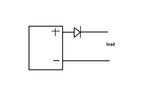
i want to know how we can protect our circuit from reverse polarity problems...

then what will happen if we apply a dc voltage in to the input of a rectifier...i think a rectifier can help us from reverse polarity...am i correct...please do reply
 
Last edited by a moderator:

Do you think that the probability to receive an answer to your question increases with larger font size?
Please use the normal font size as anyone else, we are not blind.

If your question is about a rectifier bridge using four diodes then what you say is correct, depending on the input polarity only two of the diodes will conduct and the output polarity will be always the same BUT you will also have an output voltage which will be lower compared to the input because of the voltage drop of the two diodes.

Alex
 

happy to know that u r not blind...then it was my pblem..i was not knowing that this font size is intended for blind peoples...


if we r using rectifier then the output will be lower than input...then hw we can get rid off this reverse polarity pblem?
 

You can also use only one diode in series with the power supply (usually the positive side), if the voltage input is reversed then the diode will not conduct and the circuit will be protected.
In that case the device will not work when the input is reversed.

Alex
 

ok...am using a diode in series with my supply, to positive terminal p side nd between n side nd ground my circuit...if the supply voltage is 5 i will get 4.3 at diode output rit?
 

u mean dis
 

Attachments

  • Untitled.jpg
    Untitled.jpg
    20.2 KB · Views: 67

happy to know that u r not blind...then it was my pblem..i was not knowing that this font size is intended for blind peoples...
I don't find this funny, there are certain rules to the forums that you must follow.
And I don't like you making fun of what I write.

ok...am using a diode in series with my supply, to positive terminal p side nd between n side nd ground my circuit...if the supply voltage is 5 i will get 4.3 at diode output rit?
You can use a Schottcy diode which will has a lower forward voltage drop.

The diode should be connected after the load input so that it stays connected to the same load polarity because if you reverse the load after the diode you are not protected.

Alex
 

Hareesh,

Forum etiquette demands that people don't shout. Usually that takes the form of posting in capital letters but using large fonts and bold typeface are also shouting. Take this as your warning.

Keith
 

There is a problem using just 2 magnets, which is that the top magnet will fall sideways unless you constrain it. To get around this, use a top magnet (N pole down) then a bottom magnet (N pole down) then a sheet of pyrolyitic graphite (or bismuth) which is diamagnetic.
 

sorry for the inconvenience..it was my mistake..i was not knowing that posting in capital letters and using large fonts and bold typeface are shouting. am new to this forum pardon me
 

Status
Not open for further replies.

Part and Inventory Search

Welcome to EDABoard.com

Sponsor

Back
Top