Continue to Site

Welcome to EDAboard.com

Welcome to our site! EDAboard.com is an international Electronics Discussion Forum focused on EDA software, circuits, schematics, books, theory, papers, asic, pld, 8051, DSP, Network, RF, Analog Design, PCB, Service Manuals... and a whole lot more! To participate you need to register. Registration is free. Click here to register now.

Help with IR repeater needed

Status
Not open for further replies.

holabr

Member level 2
Joined
Feb 12, 2010
Messages
46
Helped
1
Reputation
2
Reaction score
1
Trophy points
1,288
Location
USA
Activity points
1,719
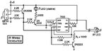
I built my own IR repeated a number of years ago and found it in the bottom of my junk bin. It was based on the GP1U52X IR detector. See the attached schematic. Can I replace the GP1U52X with the stereo Y splitter and the 2 detectors I have that came with my Comcast digital cable adapters?. What factors are involved in being able to run multiple parallel detectors? Also since these detectors are plastic encased units with a stereo (3 conductor) plug on the end, how do I determnine which pin is Vcc, Ground and Signal? Do I risk damaging it if I use trial and error to connect it to my repeater? If I can't simply connect them through a Y splitter, any suggestions on a mod to the circuit to support 2 detectors? Any help or suggestions is greatly appreciated.
 

Attachments

  • HobbyIRRepeat.jpg
    HobbyIRRepeat.jpg
    45.5 KB · Views: 104

Infra red domestic remotes tend to use 40khz 'toneburst', and aplliances often have a monolithic receiver within, whereas upon a modulated 40khz transmission the receiver module gives a logic 1 or 0 output (there is an amplifier and 40khz tone decoder within the ir receiver module).
The module your project used is monolithic and gives a logic output, according to its datasheet.
I'd expect that the little 'blips' you get with some equipment also to have a monolithis receiver module, that being the case opne of these would probably work with your circuit.
Finding the connections for the blip might be a little tricky, make a little lead plug to socket, then break out the three connections, you'll be able to suss out which is power with a meter, and the data connection will give itself away with either a scope or logic probe while you point a remote at the blip and press a button, if you havent got either then connect a speaker via a 1k resistor to the connection you'll hear the codes.
You might just need a 1k pullup resistor to the positive supply.
 

can two of these be connected in parallel using a Y connector? Also, you mentioned figuring out which pin is power using a meter. How do you do that?
 

Status
Not open for further replies.

Part and Inventory Search

Welcome to EDABoard.com

Sponsor

Back
Top