Continue to Site

Welcome to EDAboard.com

Welcome to our site! EDAboard.com is an international Electronics Discussion Forum focused on EDA software, circuits, schematics, books, theory, papers, asic, pld, 8051, DSP, Network, RF, Analog Design, PCB, Service Manuals... and a whole lot more! To participate you need to register. Registration is free. Click here to register now.

TL494 Half Bridge blowing fuse

Status
Not open for further replies.
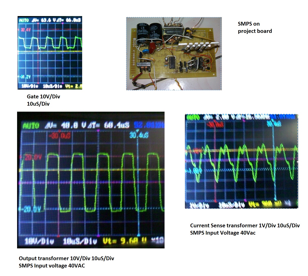
Hi thanks luben and kabiru for replying. I got a current sense transformer in series with the main transfo. The waveform almost triangular with peaks rounded with a small sort of dead time in between them. I can ttry to take a pic of it and post it here. For the frequency, the IC is set to 50KHz so the Mosfet should be switching at 25KHz
 

why is it normal to be above 10V for top MOSFET?

IV

---------- Post added at 08:54 ---------- Previous post was at 08:18 ----------

Hi Zeus

just for completnes of your design paramiters; what is the turns ratio ; P1/S1/S2 for TX1 and TX2 ?
you have no protection (OC/OV) built in (and running open loop!) ; any safety concerns?
You seem to "float" the entire ac side design! why? how do you make Gate Drive measurments? do you use differntal probes, or float the scope?

IV
 

Hi IV I am still struggling to get the main section working before adding protection and voltage loop later on afer i get the main section working at least. For the gate drive transfo its a 1:1 100 turns on EEL16 for the main transfo its 73 pri and 23 sec on an EI33 core. Scope is floated for measurements

---------- Post added at 21:30 ---------- Previous post was at 19:59 ----------

Can you please further explain issue with floating ac and how i can correct it please IV. Thanks
 

Actually ,you need to have a high impedance at switch ON.Instead of 22ohm //bulbs etc. you need to have NTC so that initial imp. is high.After a softstart the current build up and lowers the source Zin.The same will help if you have a series inductor with EE lams . or even an unsaturable choke.The softstart shall be built in .
 

What parameters did you use to calculate the turns on the main transformer?
What is your peak flux swing you allowed for?
 

I've got into this a fair way down the line I know, however you've initially shown 2 schematics, only one shows a load connected, I wonder if noise is causing your problems, with nothing on the output there will be plenty.
Have you made certian theres isnt dc on the transformer, the '494 having a flip flop means the output will be 50/50, that said I've seen blocking caps on half bridges driven by this chip.
 

Thanks for replying

I will need to re-check my calculations e-design my pc psu went off as well as a new one(very strangely) i need to wait for a replacement to be able to read the file again but i do remember i went for a peak flux density of 2400G.

Yes you are right Dr Pepper there is more exactly a damping resistor followed by a DC blocking cap in parallel with a HF bypass cap. It won't hurt to be added but even with testing at 100V there wasn't any issue with noise plus am driving it from a bipolar output which unless am wrong does not need a dc blocking cap.

As for the loading you are correct yes it was tested with no load and i can load the secondary for testing. Am waiting for the current schematic to work before adding rectification diode and forward mode inductor and DC filter choke + caps e.t.c.

AM doing this step by step I feel it will be easier to iron out the problems gradually than build a complete PSU and see all parts go in smoke
 

I think you should provide some of your design data like:
1) Expected max power thru-put
2) Core type material (to calculate losses)

Also can you post a picture of the currents through the switching devices?
 
Last edited:

Sounds like you've got a good idea of whats happening.
Everytime I've done anything like this and heard of others doing it theres usually a bag of blasted mosfets and other semis involved, so I wouldnt be to worried if you toast anything.
 

Hi E-design and Dr Pepper thanks for replying. As for the power I am not expecting more than 150W from the SMPS since the Max power for the EI-33 is around 175W from what i have seen from datasheets. Though this could be done with a flyback i still want to continue the half bridge way. As for currents I don't have a current probe but i can place a 0.22 ohm between the low side mosfet source and ground and show how the waveform looks like. Is this correct? Well Dr Pepper you're right and i did blow up some mosfets and most probably there is some more to come :) but i want to proceed step by step. There is something i forgot to mention initially the EI-33 was taken out of a pc psu it worked with 220V giving 12V ac and 2 X100W bulbs in series but the waveform was not symmetric on the scope. My design goal is to get 2X35V out of this SMPS this is why the core was rewound to 73 pri and 2X23 secondary. E-design can you please tell me the exact parameter you are looking for regarding the core i can check it and post it here. Thanks
 

I would like to know the core material grade (for example N27)
 

Hi e-design sorry for the late reply. The core is a 3C90.
 

Hi sorry for so long before posting this but attached are the waveforms
Thanks
 

I don't know if it is your scope sampling rate, but the switching times appears to be slow in the displays you captured. This will cause a lot of dissipation in your devices.
I would like to see much faster edges on the gate waveforms.

Current waveform also looks suspect. How did you measure this?
 
Last edited:

Hi e-design thanks for the reply. Do you think the gate signal could have a slow rise time due to the gate transformer or anything that you could please suggest to improve the signal? Regaring current measurement i have re-used a current sense transformer from an SMPS in series with my main transformer.

One thing i forgot to do properly is that i did not switch the attenuator on my probe to prevent the probe capacitance from affecting the circuit when measuring the gate signal and for the current sense. I will correct this and post the waveform here.
 
Last edited:

Can you show the gate signals with the gates disconnected?
The current waveform is not what I would expect to see.

Do you have a DC blocking cap in your design like shown below?


Hi e-design yes its included a 1uF cap in series with my EI33 core its in my schematics. I noticed a strange thing while connecting my probe on x10 to the primary side of my gate drive transformer. On x1 it would not buzz but on x10 it would... very strange. I am currently rechecking the BD139-140 totem pole. Regarding the slow rise seems it could be due to my scope i got a new one bench scope on the way that should be here within some weeks. In the mean time i can post details of my gate drive transfo calculations just to check. I will get the data and post it here. I feel it was the gate drive that was buzzing before the fuse blew up
 

First set of info transformer is an EEL16 with 1: turns ratio 100 turns primary and 100 turns on each secondary info for core is what i managed to get in attachment. I am not sure if the turns are set properly i was going for ~2mH


What bandwidth is your oscilloscope? Those edges look so smooth and slow that it's hard to believe the scope is capturing it properly. 1us rise and fall times are very, very slow (unless you are soft switching, which I doubt you are).
 

Can you post a skectch of the complete circuit as you now have it? It would be much easier to sort out the remaining issues that way... Regards, Orson Cart.
 

Status
Not open for further replies.

Part and Inventory Search

Welcome to EDABoard.com

Sponsor

Back
Top