Continue to Site

Welcome to EDAboard.com

Welcome to our site! EDAboard.com is an international Electronics Discussion Forum focused on EDA software, circuits, schematics, books, theory, papers, asic, pld, 8051, DSP, Network, RF, Analog Design, PCB, Service Manuals... and a whole lot more! To participate you need to register. Registration is free. Click here to register now.

Variable resistor for DC motor control

Status
Not open for further replies.

rotorgoat

Newbie level 2
Joined
Apr 3, 2011
Messages
2
Helped
0
Reputation
0
Reaction score
0
Trophy points
1,281
Activity points
1,307
I have a 28V fan that is rated at 16 Amps and I would like to be able to adjust its' speed rather than using fixed resistors for Hi, Med & Lo. The origional application for this fan used 3each 1 Ohm, 100 Watt in parallel for the Low speed and direct connection for Hi speed. I've tested it on my bench with a variable power supply and the fan starts at about 9 VDC and of course increases to max at 28VDC.
What would the spec's be for a V/R reostat capable of handling this load? Also what suppliers would have this available?
 

do you want to control the speed using rheostat or by any other method?
 

Hi,

Speed control using resistors is not correct approach techincally because you are controlling voltage where as for DC Motors you need to control current. So I think you should look for current control instead of voltage control(this is only AC motors).
Thankyou
 

If you really want to put in a rheostat, you should figure out what the voltage vs. current relationship looks like for your motor. Since you have a variable power supply, take some points from 0-28V using a voltmeter (across the motor) and ammeter. From those points, you can determine the maximum power that would be dissipated by the rheostat.

One point, for example:
If Vmotor = 16V and I = 4A
In this condition, the rheostat would see 28V - 16V = 12V. So it's power dissipation would be 12V * 4A = 48 Watts. The resistance would be 12V/4A = 3 ohms.

Do that for about 10 points and see what the max dissipation and min/max resistances would be. I'd look at Digikey, Newark, Arrow, etc for suppliers, unless you have an electronics store in your city... sometimes they sell parts for appliances, and have shelves of general electrical components, too (like Radio Shack, but with more selection).
 

do you want to control the speed using rheostat or by any other method?

Well I'm open for suggestions for another means of speed control for the motor. I need it to be small enough to fit in a panel, i.e. rotary switch or rheostat.

---------- Post added at 18:22 ---------- Previous post was at 18:19 ----------

Hi,

Speed control using resistors is not correct approach techincally because you are controlling voltage where as for DC Motors you need to control current. So I think you should look for current control instead of voltage control(this is only AC motors).
Thankyou

What device would you use to control current that would meet my needs?

---------- Post added at 18:31 ---------- Previous post was at 18:22 ----------

If you really want to put in a rheostat, you should figure out what the voltage vs. current relationship looks like for your motor. Since you have a variable power supply, take some points from 0-28V using a voltmeter (across the motor) and ammeter. From those points, you can determine the maximum power that would be dissipated by the rheostat.

One point, for example:
If Vmotor = 16V and I = 4A
In this condition, the rheostat would see 28V - 16V = 12V. So it's power dissipation would be 12V * 4A = 48 Watts. The resistance would be 12V/4A = 3 ohms.

Do that for about 10 points and see what the max dissipation and min/max resistances would be. I'd look at Digikey, Newark, Arrow, etc for suppliers, unless you have an electronics store in your city... sometimes they sell parts for appliances, and have shelves of general electrical components, too (like Radio Shack, but with more selection).

I've played a little using the voltmeter and hooking it up with a 1 Ohm 100 Watt resistor and a 2.5 Ohm 100 Watt resistor in combinations of series and parallel. They get a little too warm for my comfort. I don't have an ammeter capable of measuring those kind of amp loads. My power supply goes from 0 to about 18 VDC and I have a battery charger (24V) but it only puts out 6 amps max.
 

I think you should not use variable resistor. Instead try to use PWM for motor speed control.
 
  • Like
Reactions: IanP

    IanP

    Points: 2
    Helpful Answer Positive Rating
I don't have an ammeter capable of measuring those kind of amp loads.

Use shunt resistor together with a standard voltmeter ..
Something like 0.01ohm-to-0.1ohm .. if you don’t have one like that try to connect several 1ohm (or less) resistors in parallel ..

And I agree with others that the Pulse-Width-Modulation (PWM) would be the way to go ..

IanP
:wink:
 

What device would you use to control current that would meet my needs?


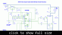
Well here is a single chip Mosfet 20A DC motor control schematic. Please note that this has short circuit protection also.

Thankyou


resistor method of control is simple to make but power wasting method.

instead , i suggest to go for PWM method of control.

if you are good at microcontroller , you can make one by yourself .
or construct a simple PWM controller with discretes or ICs with power mosfet.

the second method can be constructed with a little bit of construction experience.

which one you choose , post your requirement .
members will give their ideas.
 

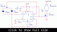
A 555 and a MOSFET should be all that is required for a PWM control.

Keith
 

yes.as suggested by keith1200rs , a 555 and a mosfet is the low solution.

if you want to have an idea refer ,
https://www.edaboard.com/threads/149740/

contains the 555 timer based pwm control circuit.

---------- Post added at 08:06 ---------- Previous post was at 08:05 ----------

please read " low solution " as "low cost solution"
 

Yes here it is as told by Keith but it will be only one direction, I think so. I have never used it. This is the simplest and you can replace that MOSFET to whatever curent ratings you need. I will not talk about back emf here.


Thank you

PS I think this will appear in the other post as well as mentioned above.


WOW: We are missing something that is most important and it is the voltage of 555 which is 18V MAX and we have 28V DC and the motor runs full speed at 28VDC and is rated at 16A. IF we are using 555 means another few components addition. So the if we are looking cost wise it is more or less the same with SG3526 :)
 
Last edited:

Status
Not open for further replies.

Part and Inventory Search

Welcome to EDABoard.com

Sponsor

Back
Top