Continue to Site

Welcome to EDAboard.com

Welcome to our site! EDAboard.com is an international Electronics Discussion Forum focused on EDA software, circuits, schematics, books, theory, papers, asic, pld, 8051, DSP, Network, RF, Analog Design, PCB, Service Manuals... and a whole lot more! To participate you need to register. Registration is free. Click here to register now.

Sim900 auto-Power down after network registration

Status
Not open for further replies.
Ok, after sending it the commands you said to, this is what I got:

Code:
+CENG: 1,1

+CENG:0,"0181,18,255,310,15,01,f809,31122,00,00,255"
+CENG:1,"65535,25000"+E:"5,5000"+N3"5,5000"+N4"5,500,"+N565,500,"+N665,500,K
I was looking at the AT commands reference sheet, but I don't really know what all these values should be, so I don't know what to make of them.
 
The first 6 fields are the important ones:
Code:
0 - [B]Cell index[/B] 
0181 - [B]ARFCN - Absolute Radio Frequency Channel Number[/B]
18 - [B]Receive Level[/B]
255 - [B]Receive Quality[/B]
310 [B]Country Code[/B] 
15 [B]Network Code[/B]
01
f809
31122
00
00
255

- Cell index = 0 indicates the data is for the serving cell; the cell you are connected to.
- The ARFCN indicates the channels being used by the module & cell. 181 indicates you are in the 850 MHz band, using 879.8 for uplink and 834.8 for downllink
- The receive level of 22 is good
- I believe the receive quality of 255 indicates the cell is not reporting that field
- Country code of 310 indicates you are in the USA, Bermuda or Guam
- A network code of 15 is not valid for the USA according to my documentation. However, a value of 150 would indicate the AT&T network.

When you send the "AT+CREG" command, are you doing it multiple times? It can take a while for the module to connect to a cell. Also, are you monitoring the Network LED? If so, what is it doing?
 

Typically the micro-controller and SIM900 are supplied through separate regulators as their supply voltages are usually different. I generally use a LDO regulator like Microchip MCP182x. If the regulator is close to the Vbat pin you don't need the extra caps. A standard USB port can not provide enough current to power the SIM900.

Hello all,
Can you guys suggest what should be the practical maximum value of the ESR value of the tantalum capacitor?

Thanks
 

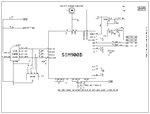
BATTERY CHARGER Interface.jpgPOWER SUPPLY Interface.JPGSIM900D Interface.JPG
Hello all,
Can you guys suggest what should be the practical maximum value of the ESR value of the tantalum capacitor?

Thanks

We are using the circuit as shown in the attached schematic. Still we find that the GSM module shuts down atleast once in every 48 hours. Sometimes, even once every 6 hours. The tantalum capacitor 330uF is having an ESR of 500 milli Ohms, & the 0.1uF capacitor is of ceramic type (not MLC) [both capacitors are placed at the power supply pins of SIM900D & are placed within 6 mm distance from the power supply pins of SIM900D]. We find by oscilloscope that the voltage is fluctuating with a peak-to-peak altitude of 100mV to 500mV, still the GSM module is functioning. Only thing is that the GSM module will shut down sometimes.

Will the performance of the system improve if we use:
1. A tantalum capacitor of 330uF 6V ESR=25milli Ohms?
2. A MLC capacitor of 0.1uF?
 
Last edited:

space a 1000uF capacitor near VBAT of SIM900. If its your circuit is PCB then what the track size of VBAT?
 

space a 1000uF capacitor near VBAT of SIM900. If its your circuit is PCB then what the track size of VBAT?

We have tried with electrolytic capacitors of 1000uF, but the same issue is still there. The track size is 2 mm thick and not more than half inches from the power plane to SIM900D's VBATT pins.
 

use an oscilloscope on VBAT and check for the spikes and noise in the VBAT.
 

We have conducted thorough tests on the matter. What we have found out in this context:

A. The GSM module shutdown occurs only when the GPRS connection is live [In our Vehicle Tracking System, when we are keeping the data upload to the server disabled and using SMS for vehicle tracking, the GSM module shut down will NOT occur]
B. In a moving vehicle, before the GSM module shuts down, the cell signal strength drops a little bit (like from 31 BER to 24 BER) followed by failure of command AT+CIPSEND, then cell switching occurs followed by network strength recovery to 31 BER, then after about one to two minutes the GSM module shuts down.
 

We have set AT+CREG=0 and it seems that the problem have solved. Now, there is NO module shutdown. We earlier noticed that during the time we issued AT+CIPSEND & the unsolicited message +CREG: 2, 1, "5678", "23DF" came, the module was shutting down...

Now we will check for AT+CREG once every 5 minutes or so, by setting AT+CREG=2 & then AT+CREG? & then AT+CREG=0... Hope this will help....
 

Status
Not open for further replies.

Part and Inventory Search

Welcome to EDABoard.com

Sponsor

Back
Top