behnam9856
Member level 3
hi,
how can i check that is module registered on a network, whenever i want?
how can i check that is module registered on a network, whenever i want?
Follow along with the video below to see how to install our site as a web app on your home screen.
Note: This feature may not be available in some browsers.
use the AT+CREG command...
 (
(If you are running the module from a LiOn battery you don't need a voltage regulator; you can connect the VBAT pins directly to the battery - this is actually preferred. You only need a regulator if you are using a power supply (like a wall wart) or a battery the puts out more than 4.8V. The layout of your grounds and power lines is critical. I have made several posts on this forum that outline the requirements and recommendations - just search for post from "GSM Man".
Here's a synopsis of what you should be concerned with:
- You need very good grounding on your PCB so that there is very voltage loss and ground-bounce. A full ground plane is highly recommended.
- You need adequate decoupling at the module BAT pins - the caps need to be physically next to the pins. I suggest a low ESR (> 10 mOhm) Tantalum cap in parallel with a .01uF MLC.
- You need a power supply that has very good transient response. The module will draw upwards of 2 A whenever it transmits. The power supply will see a huge change in the load impedance and if the transient response is not good enough its output will dip. You can have a power supply with a 20A output rating and poor transient response and still have problems.
- You need a low impedance power supply line, and your regulator should be as close as possible to the module. Like the ground plane, a full power plane is your best bet. If that's not an option, use as wide a power trace as possible. For short runs, I'd suggest at least 80-100mils.
Also, you may want to check out this video: https://www.youtube.com/watch?v=iAU_6HthM0U
- Yes, MLC stands for Multi-Layer Ceramic. The Tantalum should be at least 100mF. Some people have told me they've used a 100uF MLC in place of the .01uF MLC & Tantalum, but I haven't tried that myself.
- When using a battery, just make sure the wires between the battery and board are not too long (probably 3" max) or too thin a gauge. I was once called in to troubleshoot a design that had intermittent problems with battery leads that were 6" long. Once we shortened the leads the problems went away.
- If you want to run on batteries with a voltage below 3.6V you could use a boost-regulator to increase the voltage. However, I doubt the battery would have enough capacity left to supply the current required. Also, there are a lot of issues you need to deal with when designing that type of regulator. The easiest thing to do is to make the batteries replaceable and charge them off-line.
- If the antenna connector is far from the module then the traces between the module & antenna have to be 50 ohms. You can do this using a "micro-strip" layout. However, if the trace is short enough you don't need to be concerned with that . Just place the connector as close as possible to the antenna pin of the module and use a 20-30 mil trace to connect them. If you use a HFL or UFL connector for the antenna the trace between the pin and connector can be less than 30 mils.
2 - You can certainly use an SMA connector
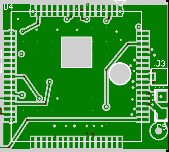
3 - You need to keep the exposed pads on the bottom of the SIM900 free of any copper. You need to place "keep out areas" in the plane under those pads. I usually put a ground plane under the module with connections to the module's ground pins. I then place a lot of vias between that plane and the full ground plane.. Below is an image of a typical layout I use.
4 - The cap value was a typo - should be 100uF.
5 - Correct on the pin connections
6 - The cap must have a low ESR (<100 milliohms) - here's one on DigiKey that meets the spec:https://www.digikey.com/product-detail/en/TPSD107K010R0100/478-1777-1-ND/564809
Digikey: https://www.digikey.com/product-detail/en/JMK316BJ107ML-T/587-1963-1-ND/1646626I definitely made a mistake not checking digikey for 100uF MLCC for the power pins.... Not sure where to find this capacitor... I am currently trying to get some from alibaba, though that might be a risk in quality if I can find it, we shall see.
The tantalum alone is NOT sufficient.I might need to sneak an 100uF 0805 tantalum with 0.01uF MLCC on somehow.... Is an 100uF 0805 Tantalum alone enough? Or should I try to put them in parallel?
I don't know about that - it may work.Just curious, do you think I could solder them bottom to bottom (to put them in parallel) and then solder the sides to the pad (instead of the bottoms)? Ugh... Design mistakes are the worst.