Continue to Site

Welcome to EDAboard.com

Welcome to our site! EDAboard.com is an international Electronics Discussion Forum focused on EDA software, circuits, schematics, books, theory, papers, asic, pld, 8051, DSP, Network, RF, Analog Design, PCB, Service Manuals... and a whole lot more! To participate you need to register. Registration is free. Click here to register now.

anyone has idea?(LED flashes on music and without music to stay turned on)

Status
Not open for further replies.

TheMrWolf1994

Newbie level 6
Joined
Mar 21, 2011
Messages
13
Helped
0
Reputation
0
Reaction score
0
Trophy points
1,281
Activity points
1,367
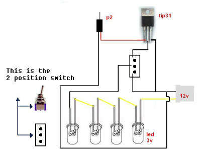
I want to make this circuit if posible with one TIP31C transistor, sound banana and 2 LED's and i want when is music turned on LED's to blink, but when not music LED's to be still turned on (cause i made it to blink but when there isn't music LED's are turned off)..and tnx in advice

Untitled.jpg
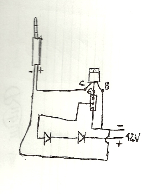
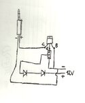
This is how I made it, but LED's turned off without music..
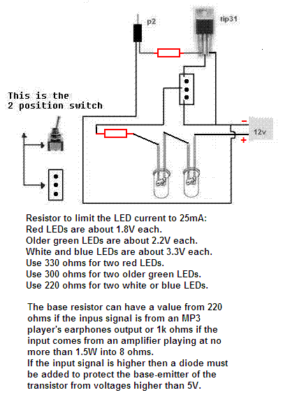
 

I am a beginner here as well but from what I can tell, your transister is turned off when the music is off.. this is probably because your MP3 player or whatever you are using is providing the DC line voltage to turn your transistor on when music is on..

one way would be to bias your transistor separately (using the 12V source) and then use a capacitor to AC couple ur music player..

if this is wrong, my apologies and i would like to know the solution as well..
 

i found one schematic for my problem here..
84_1300741991.jpg

i'm using LEDs with my computer and they are attached to the PC power suply..
i want to know will i need some resistors maybe?
 

The schematics you found are absolutely horrible garbage.
They are Instructables designed by people who know nothing about electronics.
The LED will blow up because a resistor is missing.
The music source and/or the transistor will also blow up because another resistor is missing.
The missing resistors limit the current. The author of the project knows nothing about current.
 
okey so tell me where and whick resistor I need to put..? I bought one of 680ohm for limiting current on 2 LEDs, but where to attach it, near power suply or between LEDs and switch?
 

you should probably draw out a circuit diagram, using standard circuit symbols rather than a graphic page.. then we would able to help you out...


here you go, i drew it fast just to have some better look.
 

Attachments

  • scan0001.jpg
    scan0001.jpg
    87.9 KB · Views: 116

MR. Wolf,
You show your transistor pins wrong and it is connected wrong. The base is the left pin and is the input.
Your circuit is missing the important current-limiting resistors.

The TIP31 is a power transistor. There is almost no power in this simple circuit so an ordinary smaller transistor can be used.

LED have different voltages that are dependant on their colour. I show resistor values that will make different colour LEDs bright. Your 680 ohm resistor will make the LEDs not bright.

I show an input resistor value for the earphones output of an MP3 player and for an amplifier. A diode must be added if the input is from an amplifier that plays more than 1.5W into 8 ohms.

It is a nightmare to try to attach a sketch to this website. A PNG file gave an error so this one is a GIF:

77_1300810308.gif


It
 
it's attached to the computer power suply and on computer's motherboard for sound..so can you tell me pls which resistor to put near transistor and with LEDs cause they are BLUE bright but they can work on maximum 10mA..?
 

I would suggest giving up electronics.. maybe literature?
 

I don't know if your computer has a high current output for headphones or a low current line-level output that would feed amplified speakers.
If it has a headphones output then the input resistor should be 220 ohms. Its volume control must be set very high.
If it has a low current line-level output then this circuit might not work.

Two blue LEDs are 3.3V each and a total of 6.6V. With a 12V supply the current-limiting resistor has (12V - 6.6V=) 5.4V across it. Use Ohm's Law to calculate the resistor value which is (5.4V/10mA=) 540 ohms. 560 ohms is the nearest standard value.
 

okey, i tried and made one without resistor and they worked very good..i used shematics which i posted in my 1st post..but now i want to make with 2nd shematics which i posted, i will put this one of 680ohm and then it will have 8mA so we will see..and on transistor i will put some maybe of 200ohms just in case
 

Sound produces an AC waveform but an LED operates on DC. So when the LED is as bright as is possible it is turned on for only half the total time and looks like it has a current of only 4mA, not 8mA.
 

and i think that, but now my only problem is what resistor to put on base of transistor? i can start making this circuit already, just a value i need..
 

Your first citcuit worked without burning out the LEDs or the computer's audio output because you are lucky.
Maybe your 12V has a low amount current.
Maybe the computer sound output has a low amount current.
Maybe both.

To properly design a one transistor circuit and calculate the value for the transistor's base then we need to know the max output voltage and current from the music source. Then we use Ohm's Law and simple arithmatic to calculate base current that is 1/10th the transistor's collector current and calculate the resistor value. Try 220 ohms.
 

i think that it didn't burn cause power suply from computer on 12V rail has maximum 18A, but that current is maximum which can power suply produce, so when i attached diodes i think that from 12V to the LEDs goes amount of current just needed by LEDs, nothing more. I saw on my headphones that their maximum output is 100mW and rated impedance is 32ohm, so can we maybe calculate the current here?

---------- Post added at 21:55 ---------- Previous post was at 21:42 ----------

i found some characteristics for tip31c transistor, if it can help you, here you go..
NF-L , >3MHz , 140V , 3A , 40W
 

The TIP31 is a transistor. The output current of a transistor is the amount of base current you apply to it times its current gain.
If you drove this circuit from a power amplifier then the base current will be as high as the amplifier can produce which will be amplified by the transistor which will destroy the LEDs. The current from the amplifier will probably be high enough to blow up the transistor or the amplifier or both. That is why I say that the circuit is missing two very important resistors and the circuit was designed by an idiot. A very lucky idiot because his music source was weak enough not to provide too much base current for the transistor then the output current of the transistor also was low.
 

so can i try with 680ohm on transistor and 620ohm with LEDs?
 

We don't know how much voltage and how much current comes from your music source. Maybe it can produce 100mW into a 32 ohm earphone. Then its peak voltage is 2.5V and its peak current is 79mA.
The base voltage of the transistor is about 0.7V and then the base resistor will have a peak voltage of 1.8V. A 680 ohm base resistor will limit the peak base current to 1.8V/680 ohms= 2.7mA which is fine.

With a 12V supply and two 3.3V blue LEDs then if the transistor turns on well the current in the LEDs is (12V - 6.6V)/620 ohms= 8.7mA. The circuit is a half-wave rectifier so the LEDs are turned on for only half the total time and will look fairly dim at 4.4mA.
 
okey, thank you for your help I appreciate it..i will make it so we will see what will be :) thx again ;)

---------- Post added at 20:23 ---------- Previous post was at 19:04 ----------

just a one small question pls, when is switch in the 2nd position when LEDs needs to be turned on allways, will then be maybe some problem cause then the current will go through the LEDs from + to - how much as i know the correct is from - to + so this will be indirect current through the LEDs..will it be a problem or it will work well??
 

Status
Not open for further replies.

Similar threads

Part and Inventory Search

Welcome to EDABoard.com

Sponsor

Back
Top