Continue to Site

Welcome to EDAboard.com

Welcome to our site! EDAboard.com is an international Electronics Discussion Forum focused on EDA software, circuits, schematics, books, theory, papers, asic, pld, 8051, DSP, Network, RF, Analog Design, PCB, Service Manuals... and a whole lot more! To participate you need to register. Registration is free. Click here to register now.

Atmel ADC gives wrong results

Status
Not open for further replies.

jdh_1984

Member level 2
Joined
Aug 11, 2010
Messages
52
Helped
0
Reputation
0
Reaction score
0
Trophy points
1,286
Location
Norway
Activity points
1,854
Hi
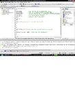
I am doing a project where a Atmel Atmega 16L(3.3V) is used as a AD converter. To start the ADC converting cycle I am using a external interrupt (INT0), and the resulting readings (10 bit) are outputted (see attachment for the code). I am using the internal 2,56V as references for the ADC reading. The problem is that the results at the output is to high compare to the voltage at the ADC input.
Here are some examples: (using the formula at page 216 in the atmega datasheet Vin=(ADC*Vref)/1024 )

The input ref signal:1.852V the digital output:776bit, which corresponds to 1.940V
The input ref signal:1.551V the digital output:647bit, which corresponds to 1.617V
The input ref signal:1.251V the digital output:514bit, which corresponds to 1.285V

What could be the reason for this inaccurate readings? I am not using any kind of filter, could this be the reason? I see the recommend an external capacitor for the AREF pin in the datasheet to improve noise immunity.

I did a new test with a voltage (3.2V) at the AREF pin as references.
I got the following results:

The input ref signal:1.826V the digital output:481bit, which corresponds to 1.503V
The input ref signal:1.551V the digital output:385bit, which corresponds to 1.203V
The input ref signal:1.241V the digital output:257bit, which corresponds to 0.803V

So something is obviously wrong, but where do I mess up???
 

Attachments

  • ADCInterrupt rev1.txt
    966 bytes · Views: 71
Last edited:

from your code i think your using Winavr/Avrgcc have you read the compiler output?
the only old Winavr/Avrgcc support the following code
Code:
SIGNAL (SIG_INT0)/*excute code when external interrupt occurs*/

replace with
Code:
ISR (INT0_vect )/*excute code when external interrupt occurs*/

if your using internal ref then to reduce noise by connecting a 0.1uf capacitor between the AREF pin and ground and LC for AVCC.

P.Ashok Kumar

Tnx for replay

I am using the studio4 compiler (I am new to uC so I just found one at Atmels homepage). The code is compiled and downloaded to the atmega16 and it is responding to the interrupt as expected. But the digital output from the Atmega 16 is given the wrong values according to the ADC input voltage (I did some tests, see my previous message). Could it be noise that causing this? Or do you have any other suggestion to what causing this problem? The resolution should be 2.56V/1024bit= 2.5mV/bit so I think I should get a closer distance between the input and the output in my tests.
 

do ypu get 0x00 when you connect the input pin to ground?

If not, then your -Vref needs to be grounded.
 

have you changed the code SIGNAL (SIG_INT0) in to ISR (INT0_vect ) and tested.
what is your micro frequency?

P.Ashok Kumar
 

after changing the code you have to clean and then compile
waht is output showing on build window can you post it
 

after changing the code you have to clean and then compile
waht is output showing on build window can you post it

Here is the build output
 

Attachments

  • forum ADC.jpg
    forum ADC.jpg
    151.6 KB · Views: 152

what triggers the INT0, is it output PortB and PortD is connected to LED and oscillator frequency??
can you put your Schematic.
 

what triggers the INT0, is it output PortB and PortD is connected to LED and oscillator frequency??
can you put your Schematic.

PortB are connected to the eight lowest outputs(LED) and PDO and PD1 represents the two MSB outputs(LED). I see on the last attachment I have the DDRD register = 0xfb, but it should be 0xf3, I have tested with 0xf3 and it gives the same results as before! To trig the INT0 I am using a switch (manual just for testing purpose) with a pull-down resistor.I am using the internal 8MHz clock. How accurate could I expect the readings to be?
 

i use to get normally 25 Milli-volt error so i use only 8bit Value
i put 0.1 ceramic capacitor between AREF Pin and GND, 10uh inductor from VCC to AVCC and 0.1 capacitor between AVCC to GND, and linear regulated power.

can you try this code.

#include<avr/io.h>
#include<avr/interrupt.h>
#include <util/delay.h>


/*ADC ISR, reads ADC*/
ISR(ADC_vect)
{
;

}

int main(void)
{

GICR=0x40; /*Set the INT0 bit to enable ext INT0*/
MCUCR=0x03; /*Set INT0 to be activate on rising edge */
ADCSRA=0xCE; /*ADC on, divide with 64, interrupt unmasked and started*/
ADMUX=0xC0; /*ADC0, internal 2,56V ref*/
DDRB=0xff; /*All B-pins set to output*/
DDRD=0xfb; /*PD0 and PD1 set to output*/
sei(); /*enable global interrupt*/

while(1)
{


_delay_ms(100); //0.1second delay

ADCSRA = ADCSRA | 0x40; /*Start next ADC conversion*/

_delay_ms(100); //0.1second delay

PORTB = ADCL;
PORTD = ADCH;


/*do nothing but wait for external interrupt*/
}

return 0;


}


---------- Post added at 02:06 ---------- Previous post was at 02:03 ----------

what is your input impedance??

---------- Post added at 02:21 ---------- Previous post was at 02:06 ----------

try the below link
View topic - [TUT] [C] Newbie's Guide to the AVR ADC :: AVR Freaks

P.Ashok Kumar
 

i use to get normally 25 Milli-volt error so i use only 8bit Value
i put 0.1 ceramic capacitor between AREF Pin and GND, 10uh inductor from VCC to AVCC and 0.1 capacitor between AVCC to GND, and linear regulated power.

can you try this code.


---------- Post added at 02:06 ---------- Previous post was at 02:03 ----------

what is your input impedance??

---------- Post added at 02:21 ---------- Previous post was at 02:06 ----------

try the below link
View topic - [TUT] [C] Newbie's Guide to the AVR ADC :: AVR Freaks

P.Ashok Kumar

Tnx again for replay
I have tested your code and this gave me the following results:

The input ref signal:1.833V the digital output:802bit, which corresponds to 2.005V
The input ref signal:1.534V the digital output:669bit, which corresponds to 1.655V
The input ref signal:1.245V the digital output:529bit, which corresponds to 1.323V

As you can see it is almost the same as the previous results. I will try with capacitor and LC filter to see if this will improve the results. The reason why I am needing a accurate result is that uC reads the value from a accelerometer to calculate the tilt angle. The range from the accelerometer is between 1V and 2.1V, maybe I should use the differential ADC mode with a fixed voltage at one of the input and the AREF pin (using op amps) and use the differential value to calculate the tilt. This would give me a better resolution. But first of all I should get this readings working.

What do you mean with input impedance? I am using a 10k pulldown resistor on the INT0 pin.

I have an atmega16L in spare, and just to test, I downloaded the code to it. The test gave almost the same results as the first uC.
I'm currently using a Fluke scopemeter to measure the voltage (so it should be reliable), but I could try another voltmeter to measure the voltage just too see that this gives the same results.
 
Last edited:

What do you mean with input impedance? I am using a 10k pulldown resistor on the INT0 pin.
No not INT0 pin it is about your ADC input PIN Connected (accelerometer output) and how accurate is your ref signal measurement .
posting your Schematic and PCB may help
 

No not INT0 pin it is about your ADC input PIN Connected (accelerometer output) and how accurate is your ref signal measurement .
posting your Schematic and PCB may help

The accelerometer I am using is from sparkfun (education board)
IMU Analog Combo Board - 5 Degrees of Freedom IDG500/ADXL335 - SparkFun Electronics . I don't know the input impedance, but I measure the resistance to be 35,5k between the accelerometer input and ground.
I don't have the schematic, I could draw one but it is so simple that it is easier to explain it;
PORTB (pin1-8) and PD0 and PD1(pin 14 and 15) are connected to the LEDs (with a 0,561K to ground for each LED). The accelerometer is connected to PAO (ADC0=pin 40) .
(See attachment for the pin configuration for atmega 16)
 

Attachments

  • Atmega 16.jpg
    Atmega 16.jpg
    57.9 KB · Views: 128

Schematic will tell lot of thing like your power supply regulator, decoupling capacitors,
ok try first with capacitor and LC filter for ADC and i hope you have provided decoupling cap near Micro controller power Supply Pins
 

Schematic will tell lot of thing like your power supply regulator, decoupling capacitors,
ok try first with capacitor and LC filter for ADC and i hope you have provided decoupling cap near Micro controller power Supply Pins

Hi
I did a discovery today, in the datasheet it is written (p.211): “VREF can also be measured at the AREF pin with a high impedant voltmeter.” I did so and measure a reference voltage = 2.488V not 2.56V as expected. When using this as references voltage the digital values are close to the input value. Why the references voltage isn't 2.56V I don't know, could it be because I am using atmega 16L with a supply voltage at 3.3V, and this influence the references voltage? Do you have a schematic over your atmega 16 with use of internal referances voltage? I guess that I mess something up with my circuit.
 

If you check table122 ,page 298 of the mega16 datasheet http://www.atmel.com/dyn/resources/prod_documents/doc2466.pdf
you can see that the internal bandgap voltage has

Vint min:2.3v typ:2.6v max:2.9v
Vcc 2.7c-5.5v

Also figure190 page320 of the datasheet shows a graph of the bandgap voltage vs temperature and Vcc

Alex


Hello I am having a similar problem with using an external interrupt.

I am trying to make the interrupt occur using a rising edge event. But when i am simulating it in proteus the interrupt executes from a logic level low as soon as the simulation starts but when i have it at logic level high and then start the simulation the interrupt will not run at the start or even if i change the sense control.

Whatever event i choose to have, say high to low, low to high, or any particular logic change the same result occurs when i simulate.

What I am doing to trigger the interrupt is a switch that has a toggle, with three terminals one to the interrupt pin the other two are to ground and 5v source(DC) respectively. In proteus I tried changing the switch transition time to very very small time .000001ms but there is still no effect.
 

Status
Not open for further replies.

Similar threads

Part and Inventory Search

Welcome to EDABoard.com

Sponsor

Back
Top