Continue to Site

Welcome to EDAboard.com

Welcome to our site! EDAboard.com is an international Electronics Discussion Forum focused on EDA software, circuits, schematics, books, theory, papers, asic, pld, 8051, DSP, Network, RF, Analog Design, PCB, Service Manuals... and a whole lot more! To participate you need to register. Registration is free. Click here to register now.

Problem with sensing the DC current passing through the IGBT

Status
Not open for further replies.

hussain_kiet

Full Member level 5
Joined
Mar 15, 2007
Messages
260
Helped
45
Reputation
90
Reaction score
28
Trophy points
1,308
Location
Karachi, Pakistan
Activity points
2,802
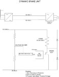
Hi i want to sense the DC current passing through the IGBT..
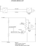
I am attaching the block diagram of the circuit..

the problem i am facing is the voltage of the DC bus can go upto 1000 V and the current through the IGBT is over 2000A.. (seriously...)
so i need a perfect method to sense the current with isolation..
Note: I cannot add a small series resistance to measure its voltage & eventually the current because the power rating required for the series resistance is way high.
the possible method which i can see is to measure the Brake Resistance voltage then current.
can some body tell me how to measure brake resistance voltage with proper isolation..?

regards,
Hussain Aftab
 

Attachments

  • Block Diagram.jpg
    Block Diagram.jpg
    46.7 KB · Views: 124
Last edited:

Re: Current Sensing...!!

I don't understand the question related to break resistor operation, because the break resistor is surely > 0.5 ohm. Also the break resistor voltage and current are effectively set by the bus voltage, that can be easily measured.

For the dimensioning of current measurement circuits, it would be important to know the rated current to calculate power dissipation. Generally, most people prefer contactless hall sensors, but low resistance shunts are an option, of course.
 
Last edited:

Re: Current Sensing...!!

well the value of the brake resistor can be less than 0.5 depends upon the braking power..
i want to measure the voltage of brake resistance do you mean that the voltage across brake resistor is almost equal to
DC bus voltage since the Rds(on) in very low in milli ohms
will it be accurate enough for over current protection..?
 

Re: Current Sensing...!!

well the value of the brake resistor can be less than 0.5 depends upon the braking power..
Of course it can, but I didn't expect that you are equipped with MW power levels.

Assuming the break resistor is well defined, measuring the DC bus voltage would be sufficient for overcurrent protection in my opinion. Otherwise, you should go for a true current measurement. But at 1000 or 2000 A rated current, shunt measurement doesn't sound reasonable.
 

Re: Current Sensing...!!

When I was working on an electric vehicle project in college, we used metal-tab current shunts to measure the current in our 108V system. They look like this (current shunts), and had resistances around 1-10 milliohms. There are many versions/values available.

A clamp-on current-transformer could work, too. Then you can set your current/voltage output by the turns ratio on the transformer.
 

Re: Current Sensing...!!

A closed loop hall effect sensor would work fine. LEM makes models that do 2000Arms just fine.
 

Re: Current Sensing...!!

well thanks for your reply..
I will consider the hall effect sensor..
A clamp-on current-transformer could work, too. Then you can set your current/voltage output by the turns ratio on the transformer.
I know the current will be varying because of PWM signal. but will it give an accurate measurement
since CT's are used to measure AC current.. ??
and for the shunt resistors even with a value of 1 Milli ohm the power requirement will be 4KW @2000A..
 

Re: Current Sensing...!!

since CT's are used to measure AC current.. ??
hall effect CT are DC transducers
and for the shunt resistors even with a value of 1 Milli ohm the power requirement will be 4KW @2000A..
That's why I said it's not reasonable. You'll get shunts down to some 10 µohm resistance, but the current range of common types is still limited to 500 or 1000 A.
 

Re: Current Sensing...!!

OK if we add a divider network across the brake resistor and then using a difference amplifier measure the divider voltage and then the current of the load which is proportional to the divider voltage....
like in the attached diagram
 

Attachments

  • Current sensing.jpg
    Current sensing.jpg
    49.9 KB · Views: 152

Re: Current Sensing...!!

Unless the differential amplifier is galvanically isolated, a symmetrical voltage divider would be needed. I still think, that measuring the bus voltage will be sufficient for overcurrent protection. The reason is simple: The IGBT on-state voltage will be either below about 2V - or it's desatured and blown within a few ms.
 

Re: Current Sensing...!!

why is a galvanic isolation needed for differential amplifier.?
I mean there is no galvanic isolation if we measuring the DC bus voltage..!!
& what is symmetrical voltage divider do you mean R1 = R2 or what.?
or two resistors in both branches.?
 

In your sketched circuit, one amplifier input is connected to the IGBT drain, so a common mode range of 1000 V would be required. Assuming an amplifier referenced to DC-, two invidual dividers seem appropriate.

I just wanted to to mention the problem, not apply for a design job. :)
 

Re: Current Sensing...!!

hall effect CT are DC transducers

That's why I said it's not reasonable. You'll get shunts down to some 10 µohm resistance, but the current range of common types is still limited to 500 or 1000 A.

A current limit of 500-1000A, sounds like you could put 2 or 3 in parallel.
2000/3 = 667 A
667^2 * 10e-6 ohms = 4.4 W each
That doesn't sound unreasonable, if you can handle the space.
 

why is it you want to measure the current? trying to determine the power dissipation? trying to protect from over current? trying to get some historical data? maybe there is another way to achieve the same goal.

for PWM you will need a current sense method with a bandwidth 10 x's the PWM frequency i would think in order to measure the peaks and valleys. i like the hall effect method because you get isolation, dynamic performance and no power dissipation problem. the LEM solution is bulky though.. but maybe is ok in your application.

looks like you are trying to do some dynamic breaking to protect the bus from over voltage during regeneration of the motor. if i were doing this... i wouldn't be measuring the current through IGBT.. i would be measuring the bus voltage and then use that to determine IGBT break ON time, with hysteresis of course. the resistor would be sized to dissipate the power and then do some calculations to determine adequate PWM time for average power loss in resistor during break time. you can get in the ball park with this method when you also measure DC bus voltage (much easier to do than to measure current through IGBT). two op-amps connected differentially will do this, just have a string of 100K resistors to drop down the voltage.

Mr.Cool
 
Last edited:

Status
Not open for further replies.

Similar threads

Part and Inventory Search

Welcome to EDABoard.com

Sponsor

Back
Top